

Electromagnetic flowmeter
- Summary
- Abstract
- Description
- Claims
- Application Information
AI Technical Summary
Benefits of technology
Problems solved by technology
Method used
Image

Examples
first embodiment
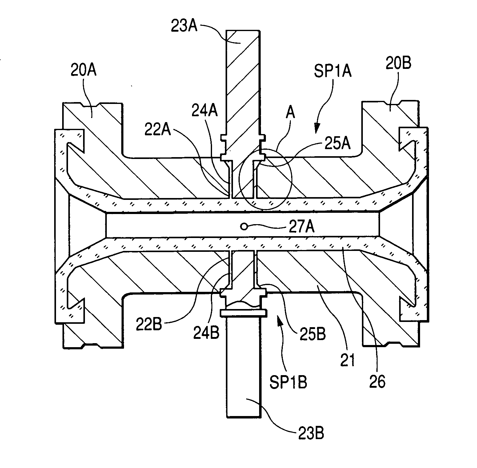
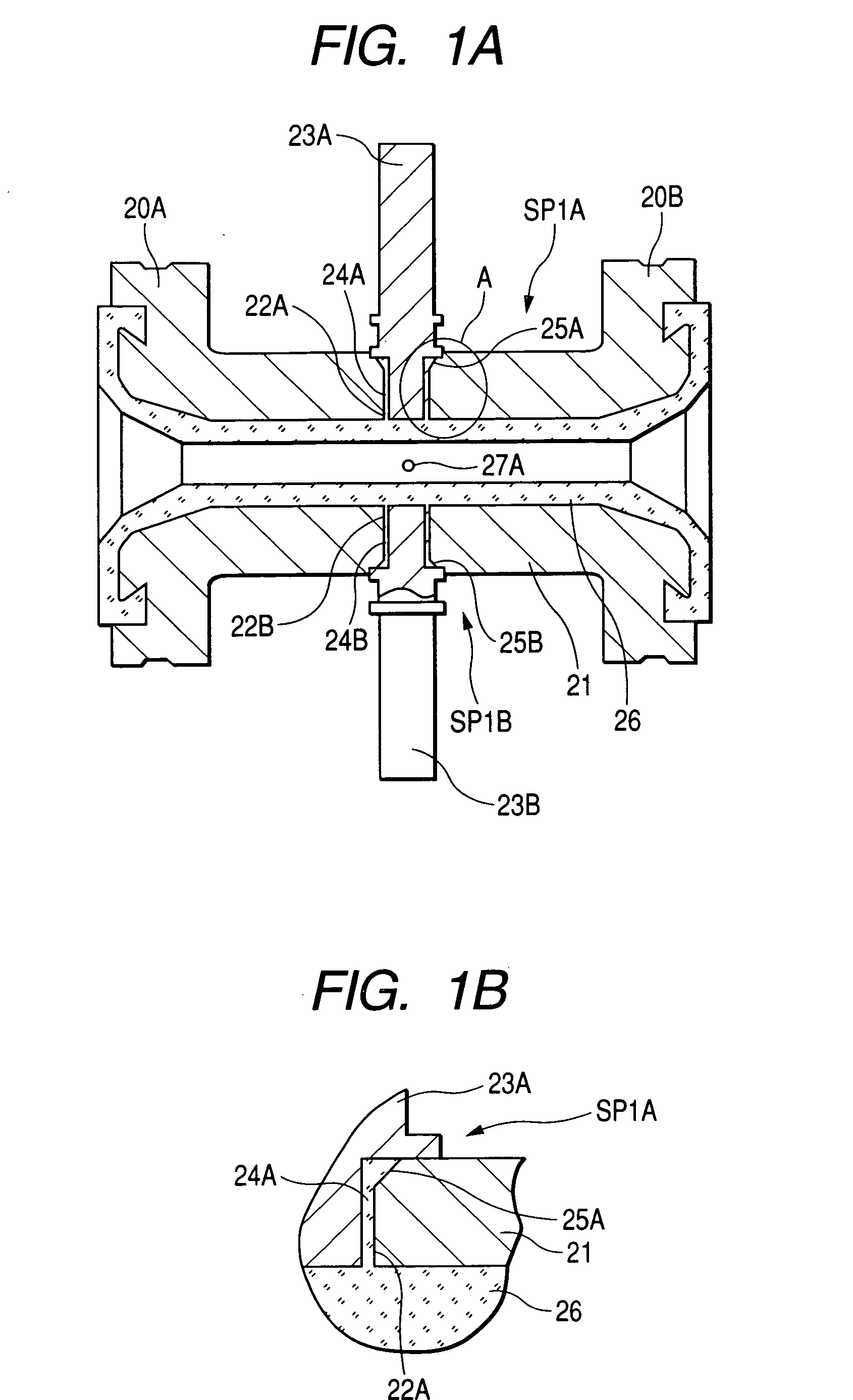
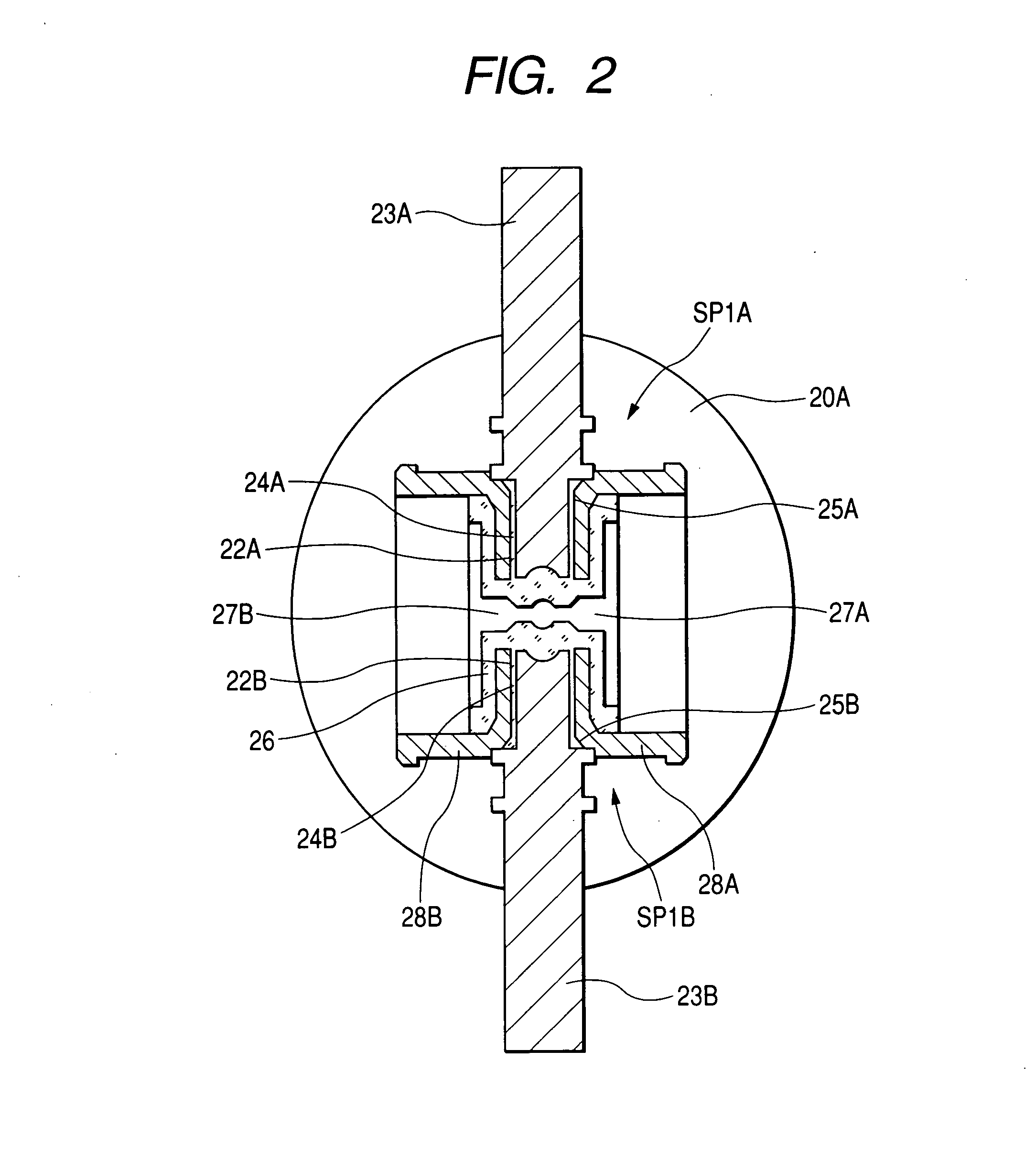
[0115]FIG. 1A is a vertical cross-sectional view of the structure of the essential portion of a measurement pipe according to a first embodiment of the invention. FIG. 1B is a detailed diagram showing a portion A in FIG. 1A. FIG. 2 is a transverse, cross-sectional view of the center portion of the measurement pipe in FIGS. 1A and 1B.
[0116] In FIGS. 1A, 1B and 2, flange portions 20A and 20B are formed at the respective ends of a cylindrical measurement pipe 21 made, for example, of stainless steel. Insertion holes 22A and 22B are formed opposite each other, in the center portion of the pipe shaft of the measurement pipe 21.
[0117] While predetermined gaps 24A and 24B are maintained relative to the insertion holes 22A and 22B, magnetic pole cores 23A and 23B which have (for example) a cylindrical shape are inserted into the insertion holes 22A and 22B and are securely welded to the outer ends of the insertion holes 22A and 22B.
[0118] These outer ends are formed so that the insertion...
second embodiment
[0123]FIG. 3A is a vertical cross-sectional view of the structure of the essential portion of a measurement pipe according to a second embodiment of the invention. FIG. 3B is a detailed diagram showing a portion B in FIG. 3A. FIG. 4 is a transverse, cross-sectional view of the center portion of the measurement pipe in FIGS. 3A and 3B.
[0124] In FIGS. 3A, 3B and 4, flange portions 30A and 30B are formed at the respective ends of a cylindrical measurement pipe 31 made, for example, of stainless steel. Insertion holes 32A and 32B are formed opposite each other in the center portion of the pipe shaft of the measurement pipe 31.
[0125] While predetermined gaps 34A and 34B are maintained relative to the insertion holes 32A and 32B, magnetic pole cores 33A and 33B, which have, for example, a cylindrical shape, are inserted into the insertion holes 32A and 32B and are securely welded to the outer ends of the insertion holes 32A and 32B.
[0126] The outer ends of the insertion holes 32A and 3...
third embodiment
[0131]FIG. 5A is a vertical cross-sectional view of the structure of the essential portion of a measurement pipe according to a third embodiment of the invention. FIG. 5B is a detailed diagram showing a portion C in FIG. 5A. FIG. 6 is a transverse, cross-sectional view of the center portion of the measurement pipe in FIGS. 5A and 5B.
[0132] In FIGS. 5A, 5B and 6, flange portions 40A and 40B are formed at the respective ends of a cylindrical measurement pipe 41 made, for example, of stainless steel. Insertion holes 42A and 42B are formed opposite each other in the center portion of the pipe shaft of the measurement pipe 41.
[0133] While predetermined gaps 44A and 44B are maintained relative to the insertion holes 42A and 42B, magnetic pole cores 43A and 43B, which have, for example, a cylindrical shape, are inserted into the insertion holes 42A and 42B and are securely welded to the outer ends of the insertion holes 42A and 42B.
[0134] The outer ends of the insertion holes 42A and 42...
PUM
 Abstract
Description
Claims
Application Information