Systems and Components for Enhancing Rear Vision from a Vehicle

a technology for rear vision and rear windows, applied in sun visors, lighting and heating devices, instruments, etc., can solve the problems of introducing many safety concerns, significantly impaired driver's vision through the rear window, and significant increase in the risk of a driver accidentally crashing or running over something or someon

Inactive Publication Date: 2007-01-25
GENTEX CORP
View PDF57 Cites 10 Cited by
  • Summary
  • Abstract
  • Description
  • Claims
  • Application Information

AI Technical Summary

Benefits of technology

[0004] Accordingly, it is an aspect of the present invention to solve the above problems by providing a vehicle lamp assembly for providing additional illumination to the rear of a vehicle. An additional aspect of the present invention is to provide a vehicle lamp assembly that is relatively inexpensive and does not require frequent replacement of the light source.
[0007] An additional aspect of the present invention is to provide an electronic imaging system for enabling images to the rear of the vehicle to be captured with a camera and displayed to the driver on a display device. Another aspect of the present invention is to mount the camera of the imaging system to the rear of a vehicle in a location that is relatively covert and aesthetically pleasing, and that is very practical and economical from a manufacturing stand point.
[0009] Still another aspect of the present invention is to integrate a camera of a vehicle imaging system with an existing vehicle component to thereby enable such cameras to be more easily installed in a vehicle. To achieve this and other aspects and advantages, a modular integrated vehicle rear window assembly according to the present invention comprises a rear window and a camera. The camera may be mounted to an inner surface of the rear window so as to capture an image to the rear of the vehicle through the rear window or the camera may be mounted to a window frame structure in which the rear window is mounted.
[0010] Yet another aspect of the present invention is to provide a vehicle imaging system that has an enhanced ability to capture images to the rear of the vehicle whether driving forward down the road or backing up. To achieve this aspect and other aspects and advantages, a vehicle imaging system according to the present invention comprises a camera for capturing an image, a radiation source for emitting radiation to which the camera is sensitive within the field of view of the camera, and a controller coupled to the camera and the radiation source for reading the image captured by the camera at periodic intervals and for periodically activating the radiation source during intervals at which the controller is reading the image from the camera. The radiation source may emit infrared radiation while the vehicle is driving forward down a road, and / or may emit visible light when the vehicle is backing up.
[0011] Another aspect of the present invention is to reduce the adverse effects a signal light or illumination light may have on a camera that is mounted proximate to the lights. To achieve this and other aspects and advantages, a lighting and electronic imaging system according to the present invention comprises a light source mounted to the vehicle, a camera mounted to the vehicle for capturing images for display to a vehicle operator, and a controller coupled to the camera and to the light source for reading the image captured by the camera at periodic intervals and for periodically activating the light source during those intervals when the controller is not reading images captured by the camera.

Problems solved by technology

The use of privacy glass, however, introduces many safety concerns.
When such privacy glass is used on the rear window of a vehicle, the driver's vision through the rear window is significantly impaired, particularly at night.
Because the back-up lights on a vehicle do not provide sufficient illumination to the rear of the vehicle to counter the effects of the privacy glass, the use of privacy glass significantly increases the risk that a driver will accidentally back into or run over something or someone.

Method used


Image

  • Systems and Components for Enhancing Rear Vision from a Vehicle
  • Systems and Components for Enhancing Rear Vision from a Vehicle
  • Systems and Components for Enhancing Rear Vision from a Vehicle

Examples


Embodiment Construction

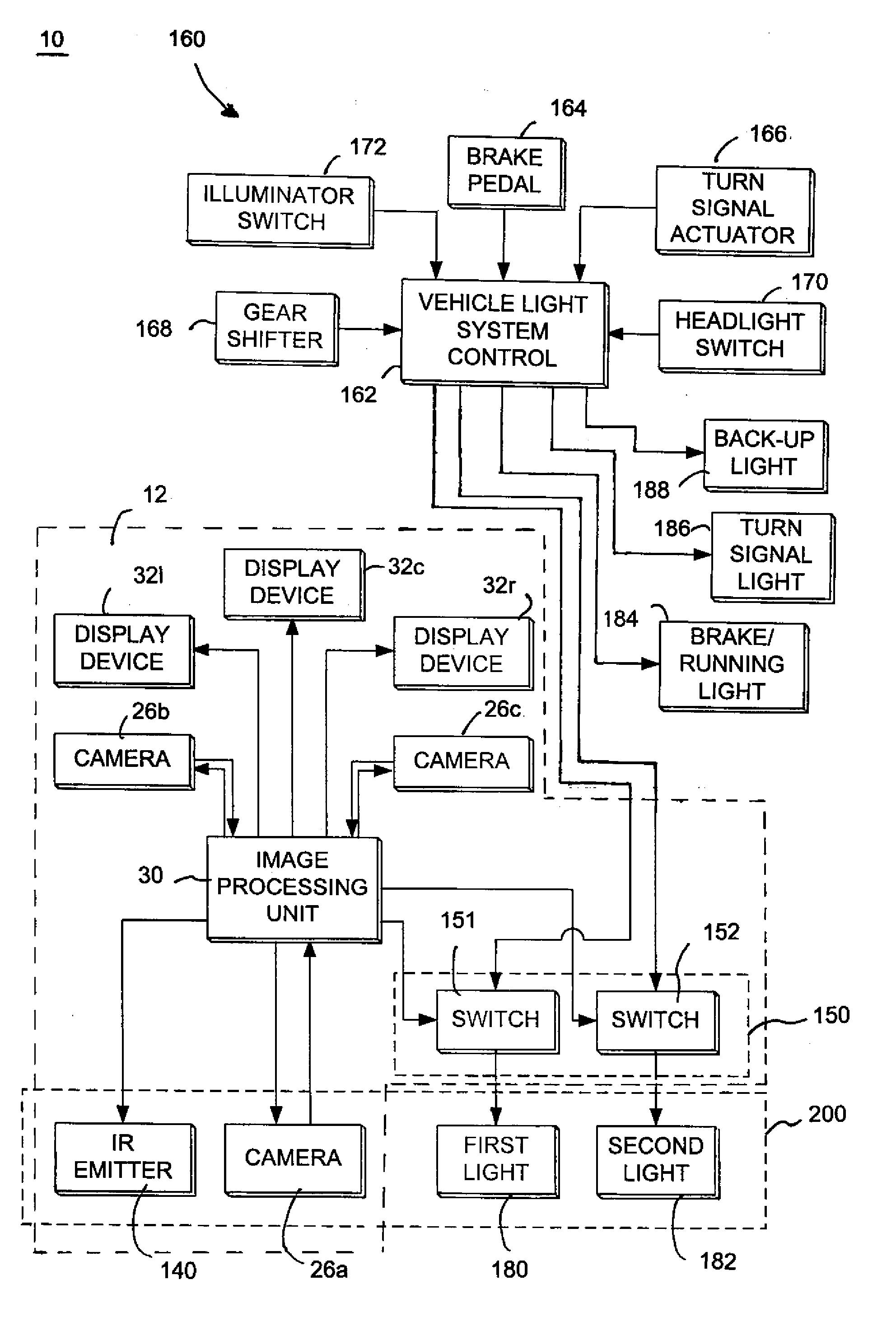
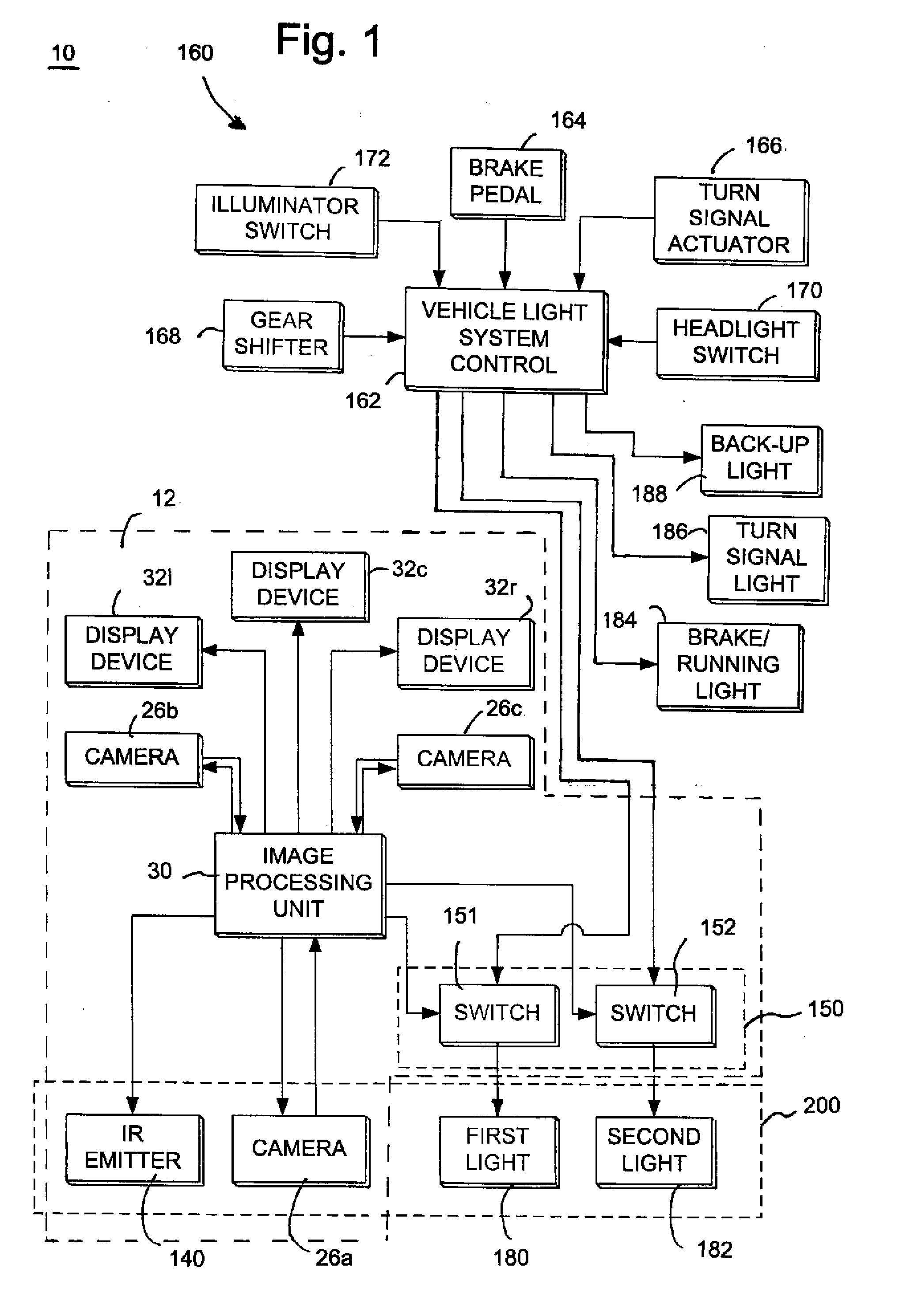
[0041]FIG. 1 shows a system diagram illustrating the various components constituting the system 10 of the present invention. As illustrated, system 10 includes an electronic imaging subsystem 12. Imaging subsystem 12 includes at least one camera 26a, 26b, and / or 26c; at least one display device 32a, 32b, and / or 32c; and an image processing unit 30. Imaging subsystem 12 may also include an ambient light sensor 34, a direct glare sensor 36, a manual intensity adjustment mechanism 116, and / or an infrared (IR) emitter 140.

[0042] System 10 further includes a first light 180 and optionally a second light 182 housed in the same assembly 200 as camera 26a. IR emitter 140 may also be housed in the same integral assembly 200. As described in further detail below, first light 180 may be a signal light such as a brake light, and second light 182 may also be a signal light or an illumination light such as a cargo light for a pick-up truck or a rear illumination light. If, for example, light 180...


PUM


Abstract

A vehicle system is disclosed that includes a vehicle lamp assembly including a plurality of LEDs that emit white light so as to function as an illuminator light. The lamp assembly also may include a plurality of LEDs that emit colored light to function as a signal light. The lamp assembly may include a camera. The lamp assembly may serve as a CHMSL or as a tail light. The system also includes a controller that rapidly pulses the LEDs at a rate that is imperceivable by the human eye. The pulsing intervals of the LEDs may be related to the readout intervals of the camera sensor array. In this manner, the LEDs may be pulsed on during camera readout to increase the illumination while the camera is capturing an image, or may be pulsed off during camera readout to prevent feedback glare from interfering with image capture by the camera.

Description

CROSS-REFERENCE TO RELATED APPLICATIONS [0001] This application is a continuation of U.S. patent application Ser. No 10 / 749,444 filed on Dec. 31, 2003, now U.S. Pat. No. 7,111,968, which is a continuation of U.S. patent application Ser. No. 09 / 724,136 filed on Nov. 28, 2000, now U.S. Pat. No. 6,672,745, which is a divisional application of U.S. patent application Ser. No. 09 / 153,654 filed on Sep. 15, 1998, now U.S. Pat. No. 6,550,949. The disclosures of the above applications are incorporated herein by reference.BACKGROUND OF THE INVENTION [0002] The present invention generally relates to systems and devices for enhancing rear vision from a vehicle. More specifically, the present invention relates to vehicle exterior illumination systems, vehicle visual signaling systems, and / or electronic rear vision systems. [0003] Privacy glass has recently become a very popular option for vehicles due to its aesthetic appearance, reduction of solar loading, and due to a belief that the privacy g...

Claims


Application Information

Patent Timeline
Patent Type & Authority Applications(United States)
IPC IPC(8): G08B13/08B60R16/02B60Q1/00B60Q1/24B60Q1/26B60Q1/30B60Q1/44B60Q1/52B60R1/00B60R1/04B60R1/12B60R11/02B63B45/00F21S8/10F21V5/02H01L25/075H01L25/13H05B44/00
CPCB60Q1/0023B60Q1/2665H01L2924/3025H01L2224/48247H01L2224/48227B60Q1/2696B60Q1/302B60Q1/52B60Q3/0226B60R1/1207B63B45/00F21S48/115F21S48/1154F21S48/215F21S48/2225F21V5/02F21Y2101/02H01L25/0753H01L25/13H05B33/0866H05B33/0872Y10S362/80H01L2224/48091H01L2924/00014H01L2924/00F21Y2115/10B60Q3/252F21S43/14F21S43/235H05B45/24H05B45/20
Inventor BAUER, FREDERICK T.BAUER, LOISROBERTS, JOHN K.STAM, JOSEPH S.
Owner GENTEX CORP
Why Eureka
Try Eureka