Air conditioning system having a terminal chest to provide optimal airflow

a technology of airflow and air conditioning system, which is applied in the field of air conditioning system, can solve the problems of inability to achieve the desired goal, inability to meet the requirements of modern time, and difficulty in energy control, and achieve optimal airflow volume, energy saving, and optimal airflow

Inactive Publication Date: 2007-01-25
COHAND TECH
View PDF9 Cites 19 Cited by
  • Summary
  • Abstract
  • Description
  • Claims
  • Application Information

AI Technical Summary

Benefits of technology

[0008] In view of the aforesaid problems occurred to the conventional air conditioning systems, the present invention aims to provide an air conditioning system with a terminal chest to provide an optimal airflow. The terminal chest according to the invention has a return air inlet which contains a first adjustable baffle. The first adjustable baffle can be opened to a desired degree according to air conditioning energy requirement alteration of each air conditioning area to regulate the second time return airflow volume, and also regulate the first time air intake volume of the air conditioning. The terminal chest has an air fan...

Problems solved by technology

While this control method is economic and simple, temperature and humidity fluctuate too much in the air conditioning area, and energy control is difficult.
It cannot achieve the desired goal.
Such an approach cannot meet the requirements of the modern time.
While this approach has some improvements in limiting the fluctuation of the temperature and humidity, the temperature of the piping fluctuates and is difficult to reach an optimal balance point when the volume of cooling and hot water changes.
Hence the temperature and humidity in the air conditioning area are difficult to reach a desired condition.
In a low sensible heat loading env...

Method used


Image

  • Air conditioning system having a terminal chest to provide optimal airflow
  • Air conditioning system having a terminal chest to provide optimal airflow
  • Air conditioning system having a terminal chest to provide optimal airflow

Examples


second embodiment

[0044] Refer to FIG. 10 for the invention. Under the structure of the previous embodiment depicted in FIG. 3, a second heat source supply device 47 (47′) is provided on a rear side or front side of the air fan motor 42 (referring to FIG. 11). This aims to lower the temperature when the temperature of the air delivered by the first heat source supply device 3 is too high (in the warm air supply condition) without reducing first time airflow delivering volume. On the contrary, when the temperature of the air delivered by the first heat source supply device 3 is too low (in the cool air supply condition), the second heat source supply device 47 (47′) can raise the temperature.

third embodiment

[0045] Refer to FIG. 12 for the invention. It aims to prevent too low of humidity in the air conditioning area A. A moisturizer 48 is added in front of the second heat source supply device 47. When the humidity value in the air conditioning area A drops below a set humidity value, the moisturizer 48 is activated.

fourth embodiment

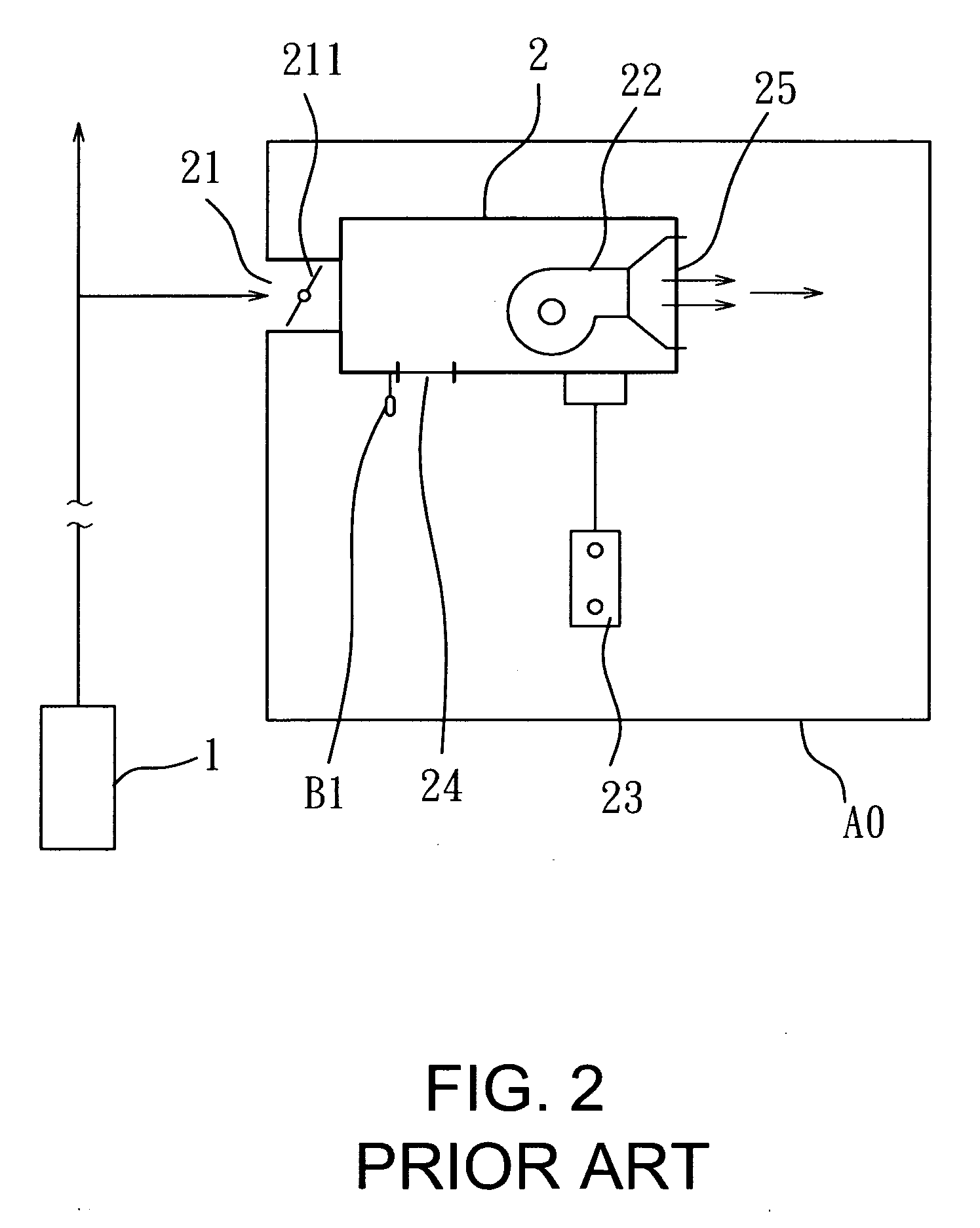
[0046] Refer to FIG. 13 for the invention. It is for a condition in which the first time air of the air conditioning is a VAV system. A first heat source supply system 6 provides required air conditioning (first time air), and a terminal chest 5 has an air vent 51 on the inlet that contains a second adjustable baffle 511. The second adjustable baffle 511 can be opened and adjusted as desired according to energy requirement of the air conditioning area A to control first time airflow volume of the air conditioning intake air. A fan motor 52 is provided to send the first time air to the air conditioning area A2 through an air outlet 55. The terminal chest 5 has a return air inlet 54 which has an adjustable cross section to provide second time return air. A setting face panel 53 is provided to set the temperature TS2 of the air conditioning area A2, and a temperature sensor B3 is provided to detect the ambient temperature TA2 of the air conditioning area A2. The return air inlet 54 has...


PUM


Abstract

An air conditioning system having a terminal chest to provide an optimal airflow mainly includes a first adjustable baffle in a return air inlet of each terminal chest that is openable to a desired degree to regulate second time return air volume and a corresponding first time air intake volume according to alterations of air conditioning energy requirement of individual air conditioning area. A variable speed air fan motor is provided that can automatically adjust the rotation speed to deliver optimal airflow volume to automatically balance the air conditioning energy supply with the air conditioning load, thereby to save energy and prevent cool air effect, and maintain a desired air quality.

Description

BACKGROUND OF THE INVENTION [0001] 1. Field of the Invention [0002] The invention relates to an air conditioning system that has a terminal chest to provide and deliver an optimal airflow volume for each air conditioning area according to airflow and air conditioning energy requirements. [0003] 2. Description of the Prior Art [0004] The conventional air conditioning system has a terminal chest 2 (referring to FIGS. 1 and 2) which delivers heat source (cool air or warm air) provided by a first heat source supply system 1 to one or more air conditioning area AO. The terminal chest 2 of each air conditioning area AO has an air vent 21 which contains an adjustable baffle 211 to control airflow of a first time air intake. An air fan motor 22 sends the air through an air outlet 25 to the air conditioning area AO. The terminal chest 2 has a return air inlet 24 on one side that has a selected cross section to provide a second time return airflow. A setting face panel 23 is provided for sett...

Claims


Application Information

Patent Timeline
IPC IPC(8): F24F3/00
CPCF24F11/0012F24F2011/0002F24F2001/007F24F11/30F24F2110/10F24F1/00075F24F11/77F24F11/76F24F11/46
Inventor WENG, KUO-LIANG
Owner COHAND TECH
Why Eureka
Try Eureka