Thrust vectoring

a vectoring and thrust technology, applied in the field of thrust vectoring, can solve the problems of limited forward speed and range of the vtol vehicle, and achieve the effect of reducing the forward thrus

Inactive Publication Date: 2007-01-25
DICKAU JOHN EUGENE
View PDF42 Cites 56 Cited by
  • Summary
  • Abstract
  • Description
  • Claims
  • Application Information

AI Technical Summary

Benefits of technology

[0044] This patent concerns a internal duct VTOL propulsion system. To establish balance in a hover lift is generated forward and aft in the aircraft center of gravity. Aft lift is developed by vectoring the aft flow of exhaust in the exhaust duct downward. Forward lift is developed by vectoring a forward air flow of air in the air intake duct downward. Using the air intake duct allows forward lift to be gen...

Problems solved by technology

The conventional helicopter is a VTOL vehi...

Method used


Image

  • Thrust vectoring
  • Thrust vectoring
  • Thrust vectoring

Examples


Embodiment Construction

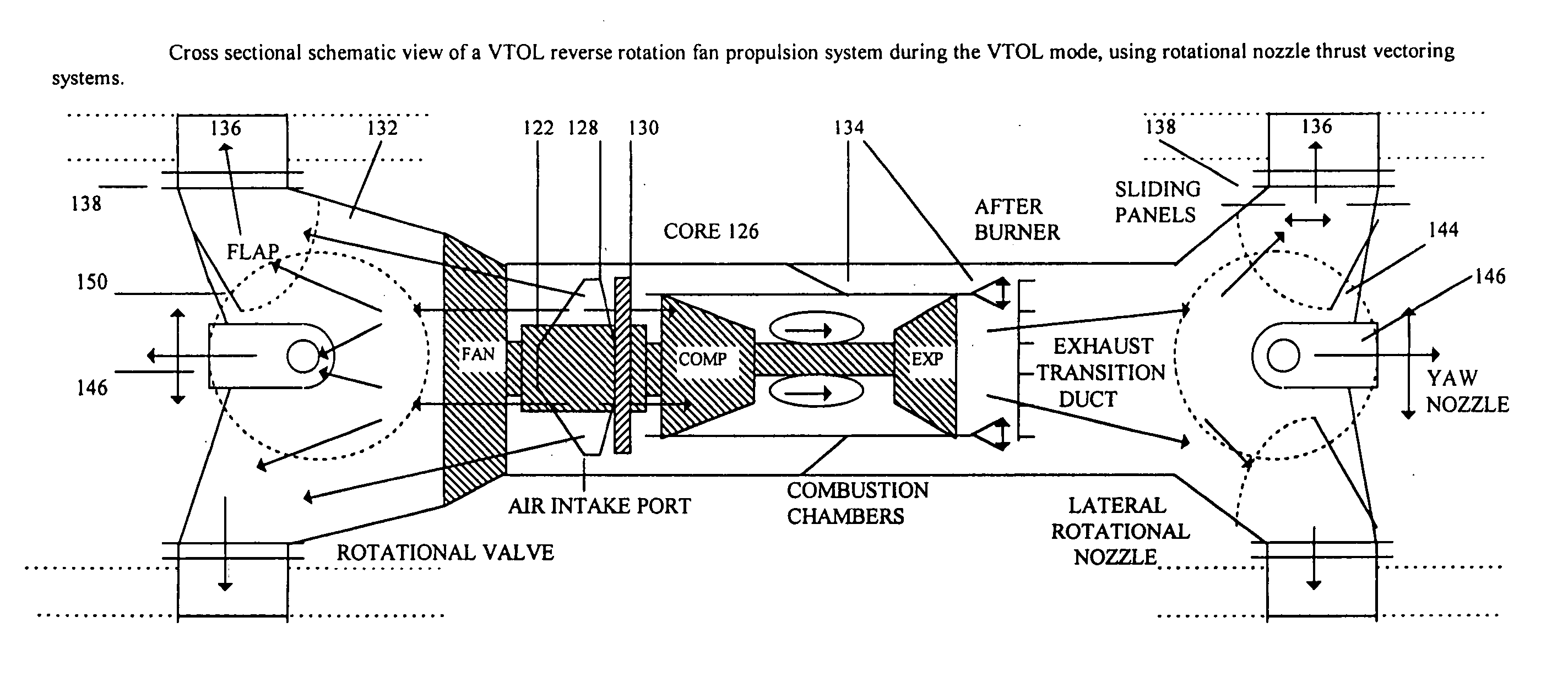
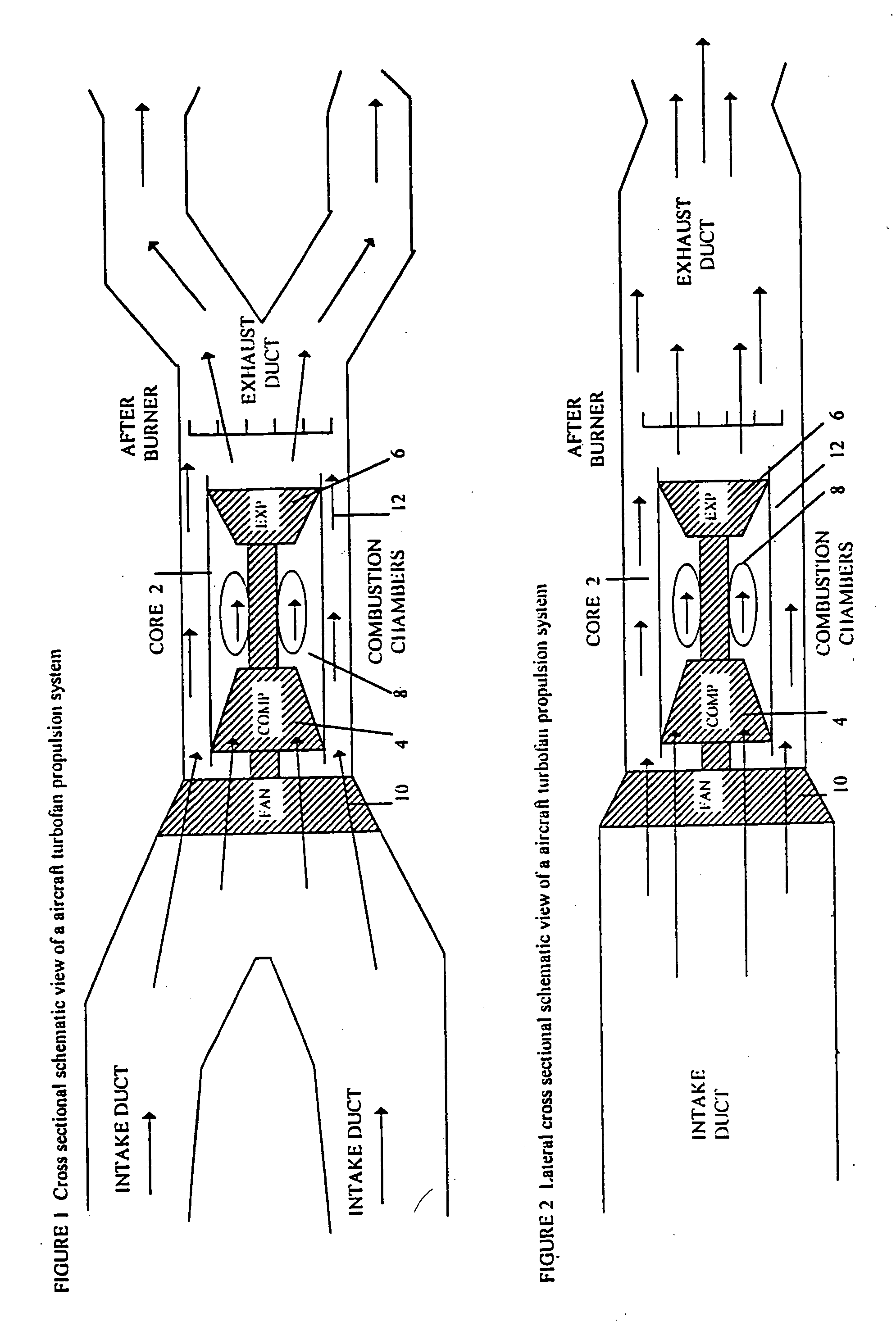
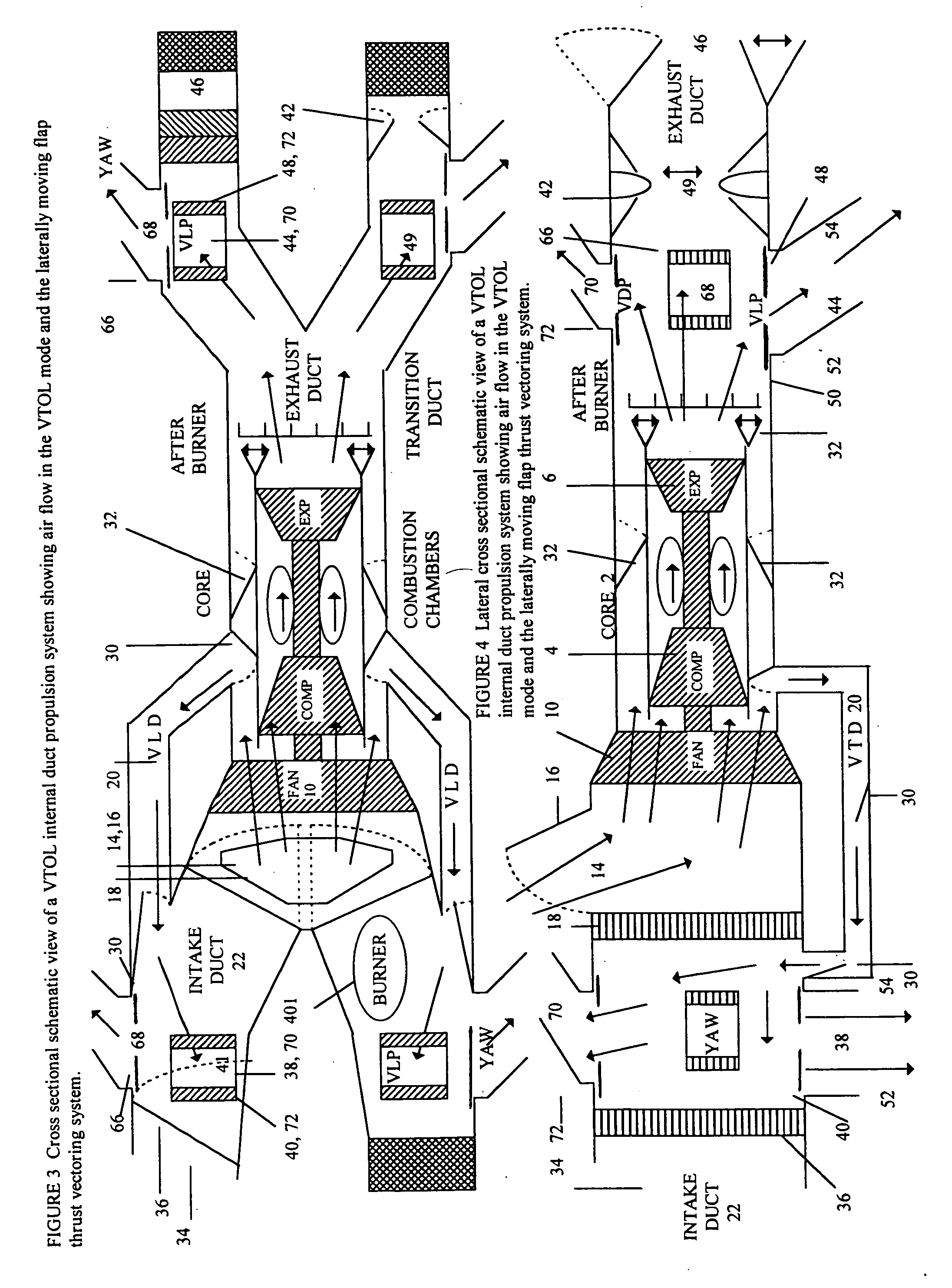
[0091] A conventional turbofan engine depicted in FIGS. 1 and 2 has a fan (10), connected to a gas turbine core (2). The gas turbine core is composed of a compressor turbine (4), a expansion turbine (6), and combustion chambers (8). The fan (10), forces air into the gas turbine core (2), and around the gas turbine core (12). Turbofan engines are referred to as high, mid, and low bypass engines depending on the ratio of air that moves through the gas turbine core and around the gas turbine core. Propulsion systems of VTOL aircraft direct the flow of air from the fan and core of a turbofan engine downward to produce lift. If the turbofan engine is located in the rear of the aircraft, air passes through air intake ducts to reach the engine. With the turbofan engine in the rear of the aircraft lift is developed behind the center of gravity of the aircraft. To balance the aircraft during VTOL lift is required near the nose. This invention uses the air intake ducts to move air forward to ...


PUM


Abstract

Thrust vectoring enhances aircraft and spacecraft maneuverability. The propulsion systems of aircraft, using gas turbine engines, and spacecraft, using solid or liquid rockets, generate compressed gases that are directed through a nozzle to generate forward thrust. This patent describes opening ports to release gases from aircraft and spacecraft in a direction other than the direction of forward propulsion. By altering the direction of gas flows leaving the craft pitch, roll, yaw and attitude control is obtained. To control gas flow from ports a variable throat thrust vectoring nozzle is described. Independent operation of ports, rotational nozzles, laterally moving flaps and rotational vanes assists the thrust vectoring of gases leaving aircraft or spacecraft ports. The ability to direct gases enhances maneuverability during vertical takeoff and landing, forward flight and space flight.

Description

CROSS REFERENCE TO RELATED APPLICATIONS [0001] This application claims the priority benefit of U.S. Provisional Application No. 60 / 312,761 filed on Aug. 17, 2001.FEDERALLY SPONSORED RESEARCH [0002] Not Applicable SEQUENCE LISTING OR PROGRAM [0003] Not Applicable FIELD OF INVENTION [0004] Thrust vectoring enhances aircraft and spacecraft maneuverability. The propulsion systems of aircraft, using gas turbine engines, and spacecraft, using solid or liquid rockets, generate compressed gases that are directed through a nozzle to generate forward thrust. This patent describes opening ports to release gases from aircraft and spacecraft in a direction other than the direction of forward propulsion. By altering the direction of gas flows leaving the craft pitch, roll, yaw and attitude control is obtained. To control gas flow from ports a variable throat thrust vectoring nozzle is described. Independent operation of ports, rotational nozzles, laterally moving flaps and rotational vanes assist...

Claims


Application Information

Patent Timeline
IPC IPC(8): B64C29/00
CPCB64C15/02B64G1/401B64G1/403F02K1/002F02K1/004F02K1/008F05D2220/90F02K1/64F02K1/74F42B10/665Y02T50/672F05D2220/328F02K1/06Y02T50/60
Inventor DICKAU, JOHN EUGENE
Owner DICKAU JOHN EUGENE
Why Eureka
Try Eureka