Panhead

a technology of a rotary body and a center of gravity position, which is applied in the field of panheads, can solve the problems of reducing the rotational speed the unit deviating from the rotational axis, and the center of gravity position of the rotary body, and achieves the effect of simple mechanism

Inactive Publication Date: 2007-01-25
CANON KK
View PDF6 Cites 19 Cited by
  • Summary
  • Abstract
  • Description
  • Claims
  • Application Information

AI Technical Summary

Benefits of technology

[0006] It is an object of the present invention to provide a panhead which is ca...

Problems solved by technology

The above conventional art, however, suffers from the problem that in a normal use mode (in which panorama shooting is not performed), the center-of-gravity position of a rotary body including the camer...

Method used


Image

  • Panhead
  • Panhead
  • Panhead

Examples


first embodiment

[0030] In the following, a description will be given of the present invention.

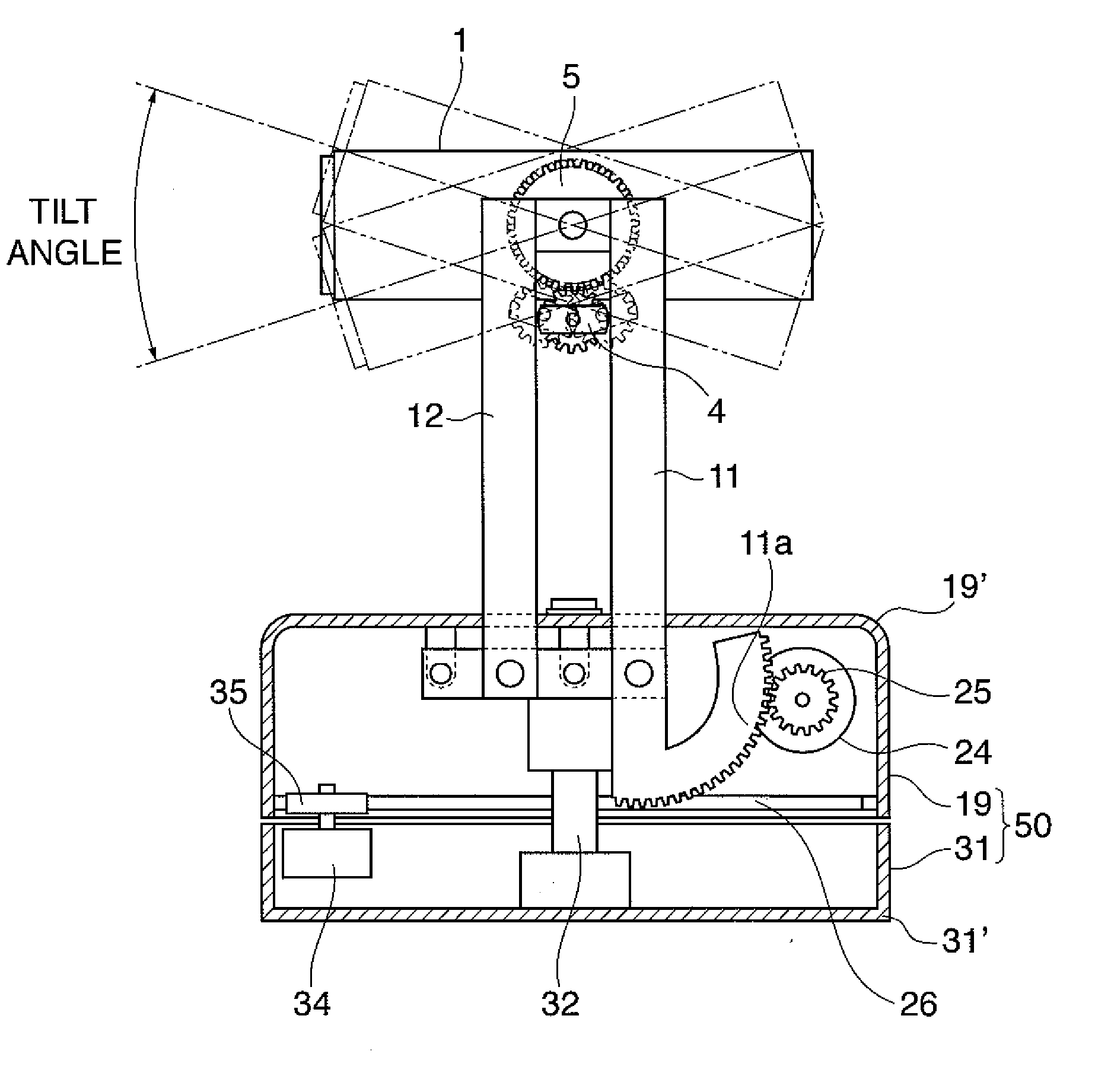
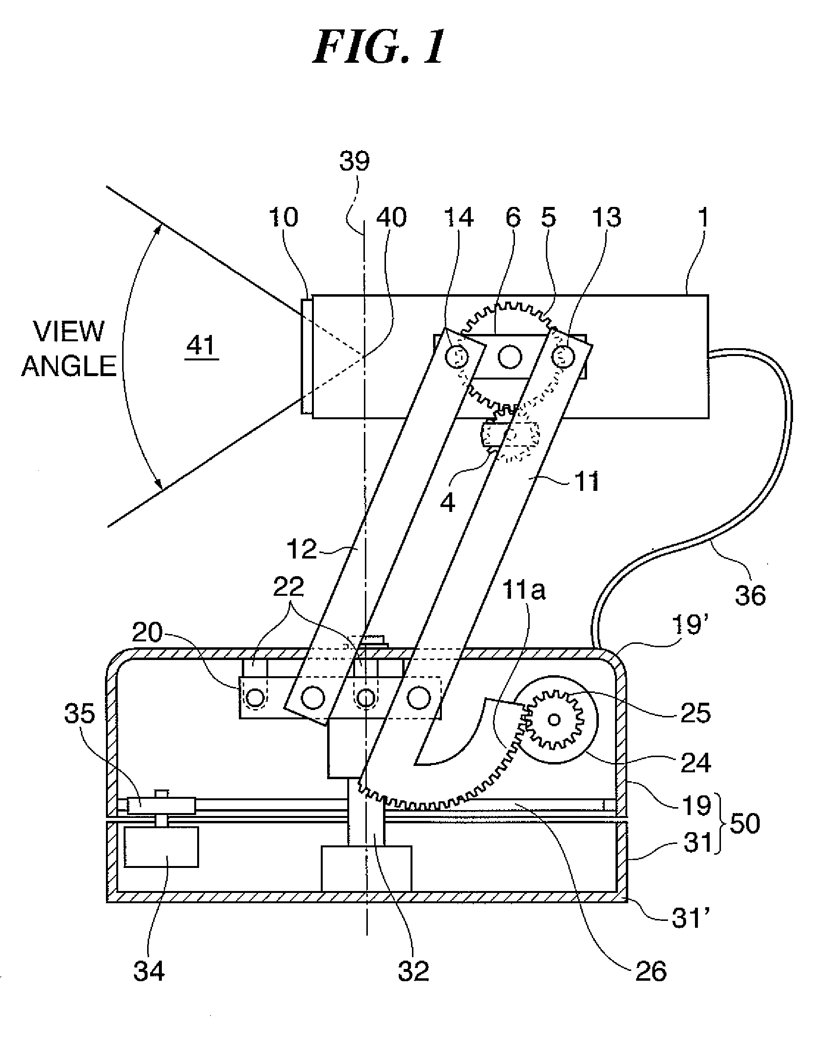
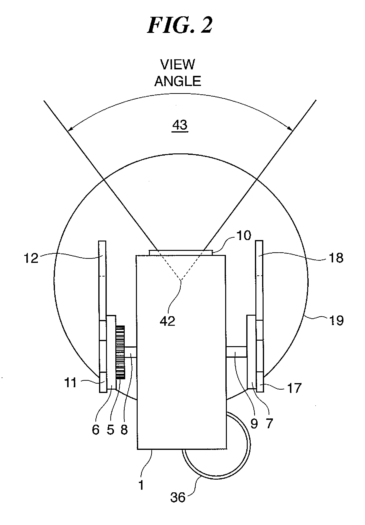
[0031]FIG. 1 is a front view of a camera-attached panhead (in a principal point position-aligned state) as a panhead according to a first embodiment of the present invention. FIG. 2 is a plan view of the camera-attached panhead, and FIG. 3 is a side view of the same.

[0032] As shown in FIGS. 1 to 3, the camera-attached panhead is basically comprised of a camera unit 1, a panhead 50, and link rods 11, 12, 17, and 18. The camera unit 1 is provided with a front lens retainer 10. The panhead 50 is comprised of a pan rotation unit 19, and a pan fixed unit 31. FIG. 1 shows of the camera-attached panhead in a state in which the lens principal point position of the camera unit 1 is aligned with the rotational axis of the same.

[0033] First, a description will be given of the construction of the camera unit 1. The camera unit 1 has a normal use mode (in which panorama shooting is not performed) and a panorama mode ...

second embodiment

[0083] Next, a description will be given of the present invention.

[0084] The second embodiment is distinguished from the first embodiment in that a slide mechanism is used for causing horizontal movement of the lens unit 1 relative to the pan rotation unit 19. Component elements identical to those of the first embodiment are designated by identical reference numerals, and description thereof is omitted.

[0085]FIG. 8 is a front view of a camera-attached panhead as a panhead according to the present embodiment.

[0086] As shown in FIG. 8, the camera-attached panhead is basically comprised of the camera unit 1, the panhead 50 having the pan rotation unit 19 and the pan fixed unit 31, and stands 43 and 44.

[0087] Between the camera unit 1 and the pan rotation unit 19, there are arranged stands 43 and 44 in facing relation with the camera unit 1 sandwiched from opposite longitudinal sides of the camera unit 1. The stands 43 and 44 rotatably hold the camera unit 1. The pan fixed unit 19 is...


PUM


Abstract

A panhead which is capable of appropriately operating an image pickup device by a simple mechanism thereof. A fixed unit is set on a base of a camera-attached panhead. A pan rotation unit is supported on the pan fixed unit, for rotation within a plane parallel with the upper surface of the pan fixed unit. Two parallel-link mechanisms connect between a camera unit and the pan rotation unit and move the camera unit to a predetermined position in which a direction of an optical axis of the image pickup device is able to be maintained, depending on the use mode of the camera unit.

Description

BACKGROUND OF THE INVENTION [0001] 1. Field of the Invention [0002] The present invention relates to a panhead for rotatably supporting a camera unit. [0003] 2. Description of the Related Art [0004] Conventionally, there has been proposed a technique related to a panhead for rotatably supporting a camera unit, which causes the lens principal point (center point) position of the camera unit to constantly align with the rotational axis of the same and provides effective means for panorama shooting (means for making joints between a plurality of images look natural) (see e.g. Japanese Laid-Open Patent Publication (Kokai) No. 2000-147643). According to the proposed technique, the lens principal point position is caused to be aligned with the rotational axis of the camera unit in accordance with movement of the lens principal point position for a focus operation or a zoom operation during a panorama shooting. [0005] The above conventional art, however, suffers from the problem that in a ...

Claims


Application Information

Patent Timeline
IPC IPC(8): H04N5/225
CPCF16M11/10F16M11/12F16M11/18F16M2200/063F16M11/24F16M2200/024F16M11/2092
Inventor IBARAKI, SHOUICHI
Owner CANON KK
Why Eureka
Try Eureka