TIR PRISM for a projection display apparatus having a partially masked surface

a projection display and prism technology, applied in projectors, television systems, instruments, etc., can solve the problems of inferior contrast, undesirable light beams, etc., to prevent stray light, improve contrast, and prevent the occurrence of stray light on the screen

Inactive Publication Date: 2007-01-25
NEC DISPLAY SOLUTIONS LTD
View PDF25 Cites 17 Cited by
  • Summary
  • Abstract
  • Description
  • Claims
  • Application Information

AI Technical Summary

Benefits of technology

[0011] It is an object of the present invention to provide a projection display apparatus which is capable of preventing stray light that may be incident on a projection lens in order to improve contrast and to prevent the occurrence of stray light on a screen in a simple structure. It is another object of the present invention to provide a TIR prism which is useful for manufacturing such a projection display apparatus.
[0013] The first shield area that is formed on the first prism surface limits the light that exits from the first prism surface such that the light exits only from the area on which the first shield area is not formed. Since the area on which the first shield area is not formed completely includes the first effective light beam area through which the modulated light path passes, the light that is essential for projecting an image through the projection lens is incident on the projection lens without being affected by the first shield area. On the other hand, stray light travels along a path that is different from the light path along which the light that is essential for projecting an image travels. The stray light that falls on the first shield area is prevented from exiting from the first shield area, and the total amount of the stray light can be reduced.
[0017] As described above, the present invention can provide a projection display apparatus which is capable of limiting stray light that may be incident on a projection lens in order to improve contrast and to prevent the occurrence of stray light on a screen in a simple structure. Further, the TIR prism of the present invention is useful for providing such a projection display apparatus.

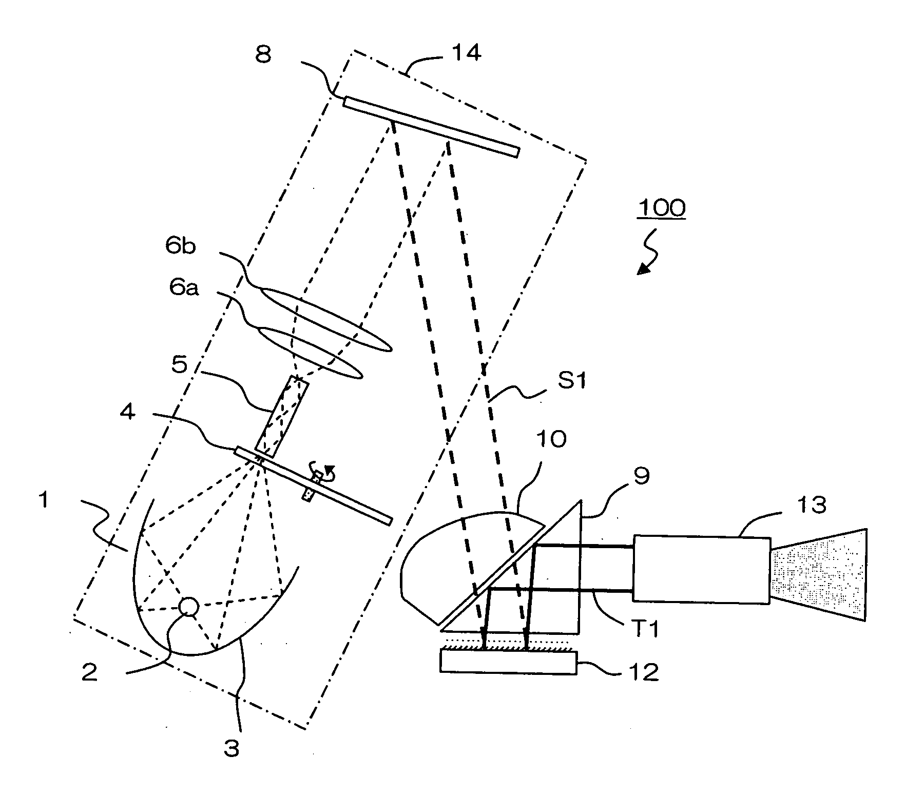
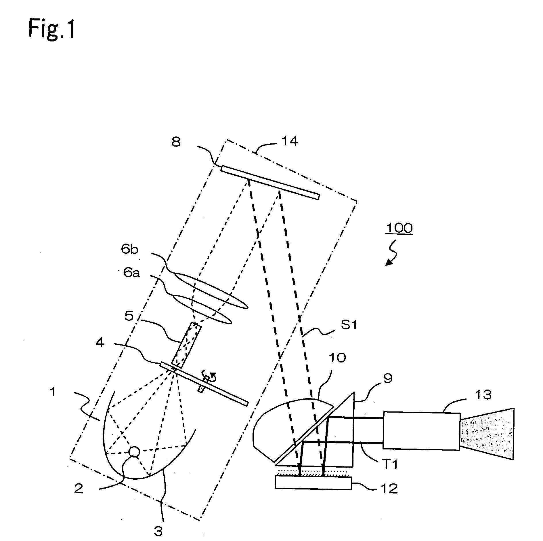
Problems solved by technology

However, the light flux that is incident on the condenser lens from a light source is not perfectly parallel, but has an angle distribution around the main light beam.
In this specification, the stray light, different from light beams which are necessary for displaying an image on a screen, means light beams which are undesirable for displaying an image.
The influence of the stray light is not conspicuous when projecting a bright image, but becomes conspicuous when projecting a dark image, resulting in inferior contrast and the occurrence of stray light on the screen.
Although the best way is to radically eliminate the cause of the stray light, it is difficult to do so for a DMD-based system due to the principle of the system.
This disadvantage is particularly conspicuous in a single TIR prism system, because the stray light tends to be more incident on a projection lens in a single TIR prism system.

Method used


Image

  • TIR PRISM for a projection display apparatus having a partially masked surface
  • TIR PRISM for a projection display apparatus having a partially masked surface
  • TIR PRISM for a projection display apparatus having a partially masked surface

Examples


example

[0066] Tests were conducted to study the conditions of the masking material and the surface of the shield area.

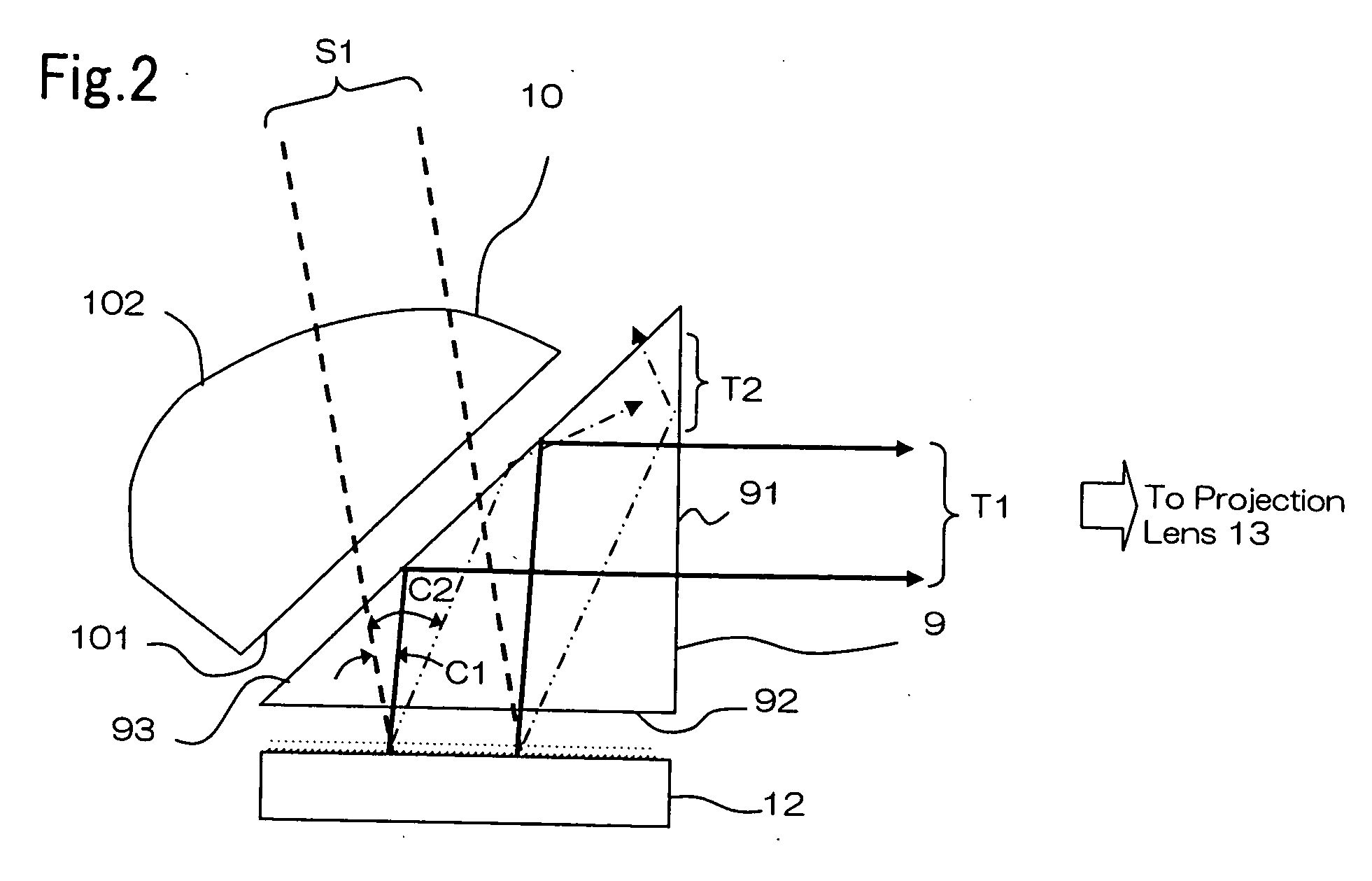
[0067] The first and the second prism surfaces of a prism and the second lens surface of a condenser lens were coated for masking. FIG. 9 shows the relationship between the incident angle and the reflectivity of a light beam that is incident on interface 2 (the masking material) which is shown in FIG. 6. Such materials as carbon (n2=1.73, k2=0.58), air (n2=1, k2=0), silver (n2=0.20, k2=3.44), and aluminum (n2=1.44, k2=5.23) are shown in FIG. 9 as examples of coating materials.

[0068] First, if the coating is formed of air (no coating) and n1>n2, then total internal reflection occurs on interface 2 for the incident angle that is equal to or larger than 41.2°. If the coating is formed of a metal such as silver or aluminum, then the light beam is not totally reflected internally on interface 2, because the refractive index is higher than that of the material of the prism. How...


PUM


Abstract

A projection display apparatus has: a TIR prism having a first prism surface, a second prism surface, and a third prism surface; a projection lens which is disposed opposite to the first prism surface; and an image display device which is disposed opposite to the second prism surface. The image display device reflects incident light in a first direction or in a second direction in accordance with an image signal. The first, second, and third prism surfaces are formed so as to define a modulated light path, wherein the light is reflected in the first direction, then is incident on the second prism surface, then is totally reflected internally on the third prism surface, then exits from the first prism surface, and then is incident on the projection lens along the modulated light path. The first prism surface includes a first effective light beam area and a first shield area for shielding the light, wherein the modulated light path passes through the first effective light beam area, and wherein the first shield area is formed on at least a part of the first prism surface except for the first effective light beam area.

Description

[0001] The present application is based on, and claims priority from, J.P. Application No. 2005-208436, filed on Jul. 19, 2005, the disclosure of which is hereby incorporated by reference herein in its entirety. BACKGROUND OF THE INVENTION [0002] 1. Field of the Invention [0003] The present invention relates to a projection display apparatus and a TIR (Total Internal Reflection) prism, and more particularly to the structure of a TIR prism which facilitates the removal of stray light. [0004] 2. Description of the Related Art [0005] A projection display apparatus modulates incident light by means of an image display device, and projects the modulated light onto a screen through a projection lens to display an image. While liquid crystal display panels have been conventionally used for image display devices, DMDs (Digital Micro-mirror Device) have recently been used for a variety of applications. A DMD, which is an image display device having many micro-mirrors which are two-dimensiona...

Claims


Application Information

Patent Timeline
Patent Type & Authority Applications(United States)
IPC IPC(8): G03B21/00
CPCG02B5/04G02B27/0018G03B21/208H04N5/7458G02B27/0972
Inventor ISHIKURA, NAOFUMI
Owner NEC DISPLAY SOLUTIONS LTD
Why Eureka
Try Eureka