
Apparatus for pivotally orienting a projection device

a projection device and apparatus technology, applied in the direction of instruments, machine supports, other domestic objects, etc., can solve the problems of limiting the amount of weight that can be mounted on the device, high inertial load, etc., and achieve the effect of simplifying the drive mechanism

Active Publication Date: 2007-01-25
STEREOTAXIS
View PDF99 Cites 113 Cited by
  • Summary
  • Abstract
  • Description
  • Claims
  • Application Information

AI Technical Summary

Benefits of technology

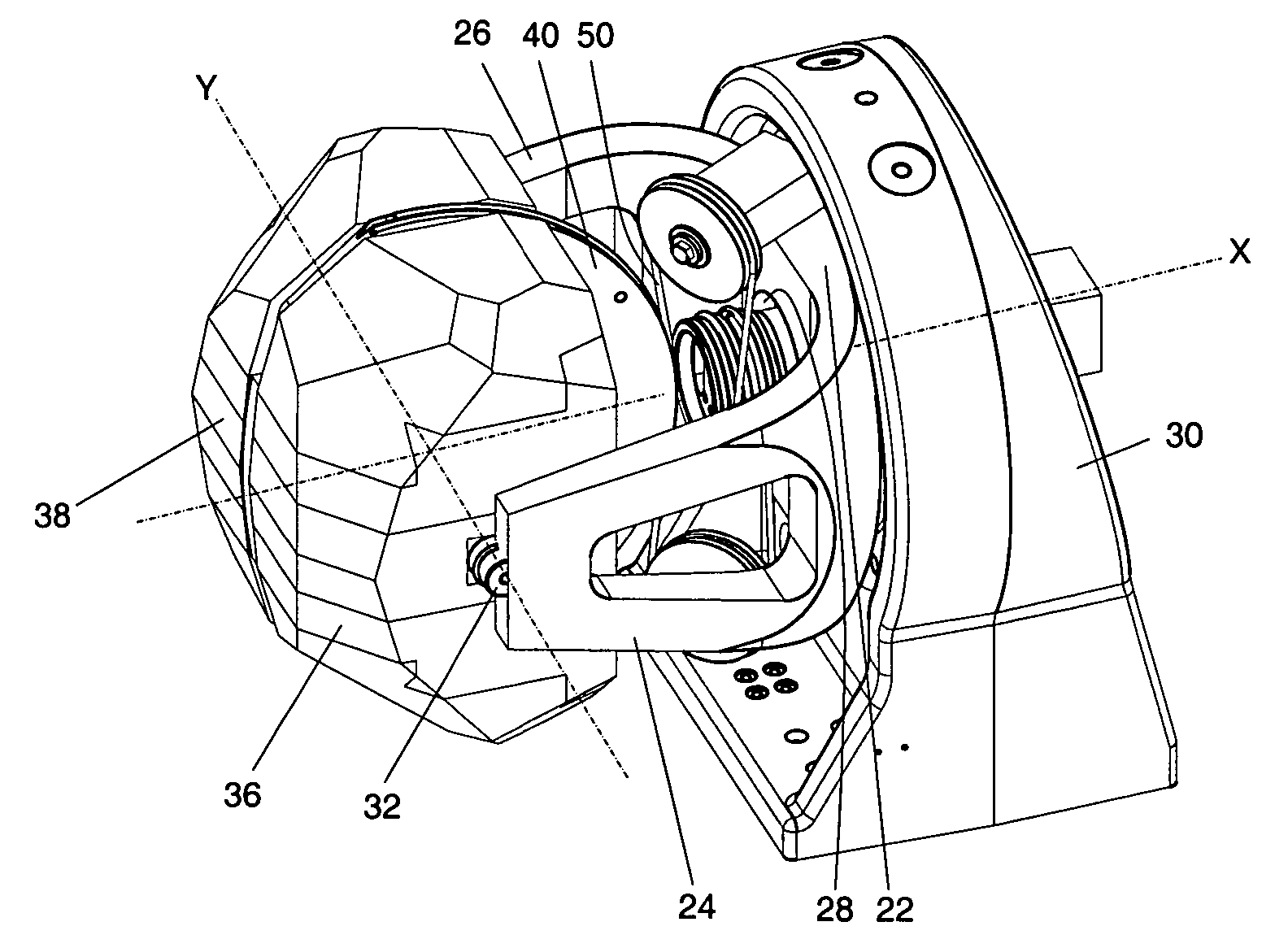
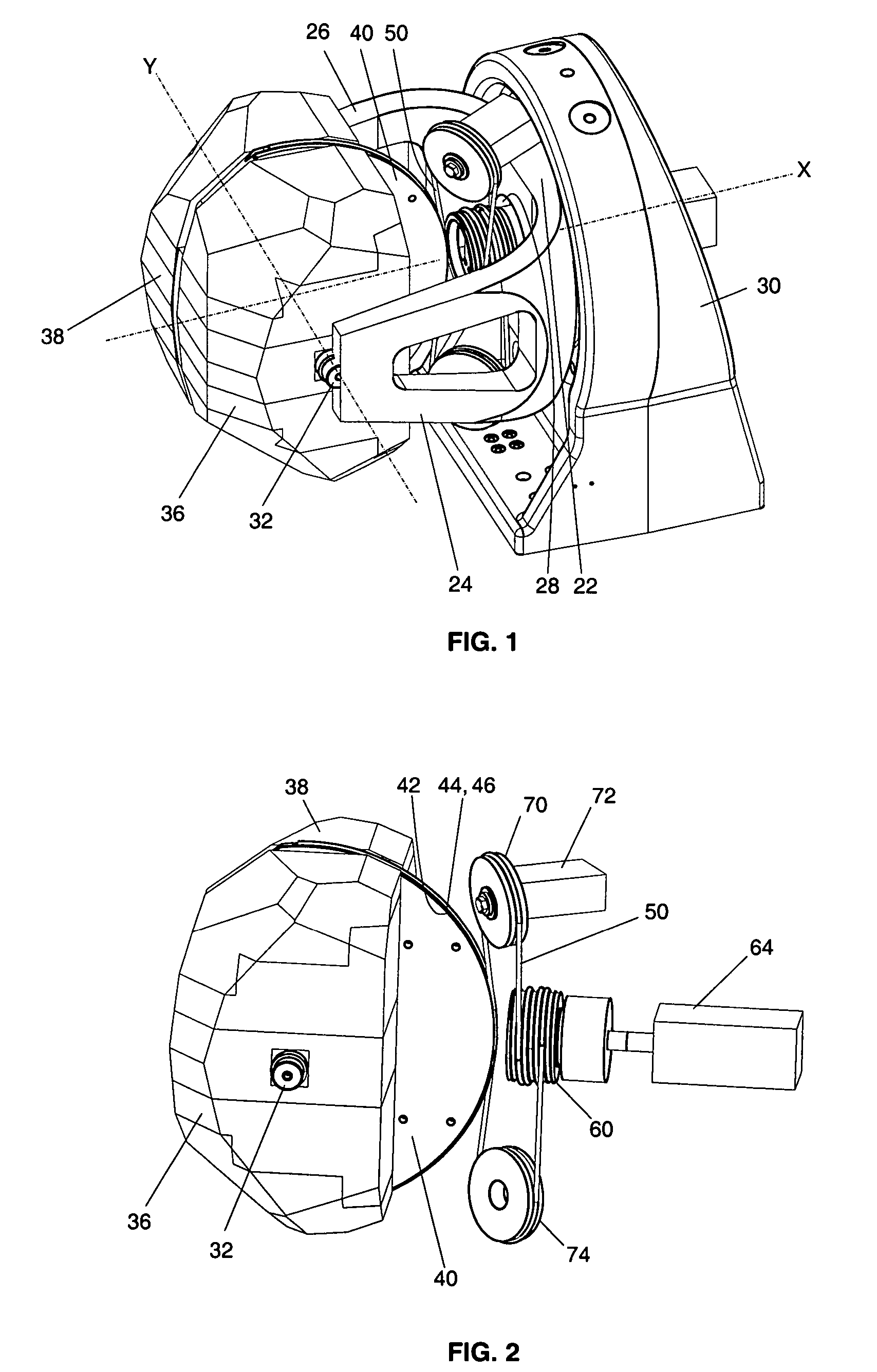
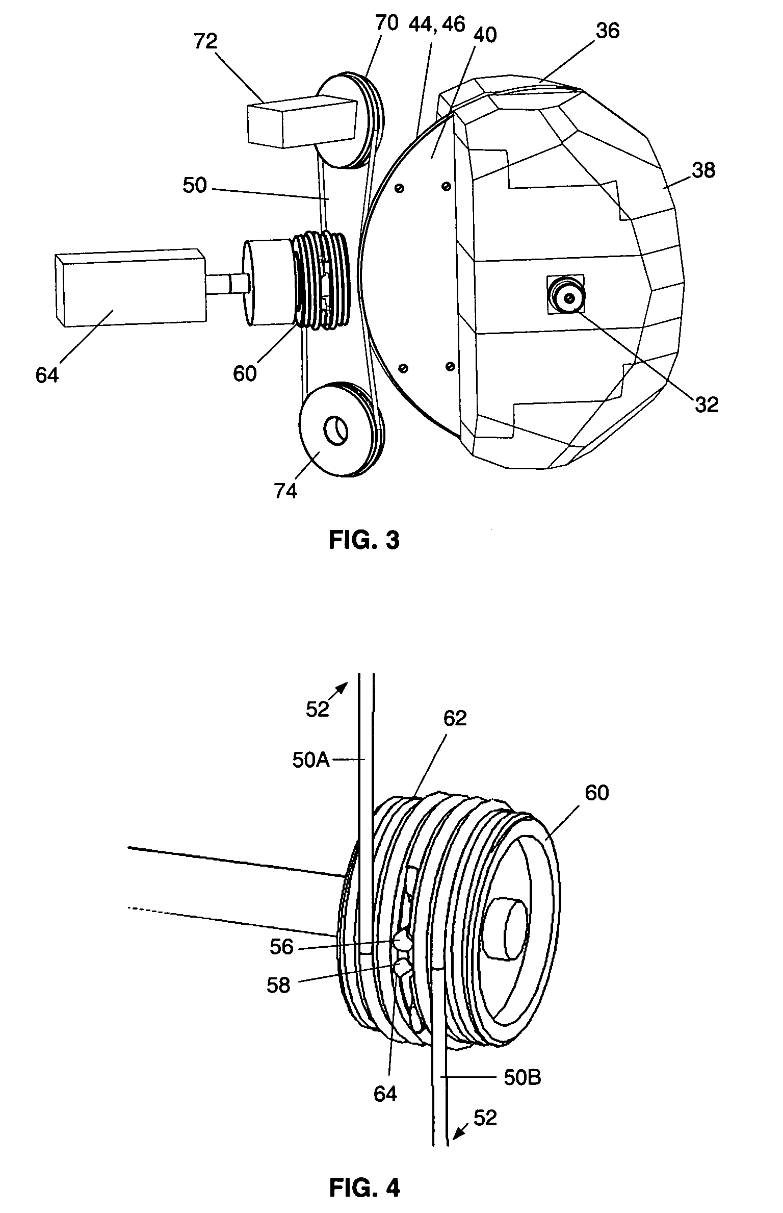
[0004] The various embodiments of the present invention provide a directional pointing apparatus comprising a simplified drive mechanism. In one embodiment, an apparatus for controllably orienting a component in a desired direction is provided that has a gimbal bracket having two laterally spaced arms adjoining a base portion that is mounted to a support base for rotation about a first axis extending through the base portion of the gimbal bracket. The first embodiment includes a mounting plate disposed between the laterally spaced arms of the gimbal bracket. The mounting plate has an arcuate edge portion with first and second parallel grooves therein adapted to receiving a drive cable. A pivot shaft is provided for pivotally coupling the mounting plate to the laterally spaced arms of the gim...

Problems solved by technology

Such pointing devices often have a significant mass associated with complex gears and drive motors for controlling the movement of the pointing device, which creates a high inertial load and limits the amount of weight that may be mounted on the device.

Method used


Image

  • Apparatus for pivotally orienting a projection device
  • Apparatus for pivotally orienting a projection device
  • Apparatus for pivotally orienting a projection device

Examples


Embodiment Construction

[0017] The following description of the various embodiments are merely exemplary in nature and are in no way intended to limit the invention, its application, or uses.

[0018] In one embodiment, an apparatus 100 for controllably orienting a component in a desired direction is provided that comprises a gimbal bracket 20 that is assembled or rotatably mounted to a base 30 for rotation about a first “X” axis. Such rotation may be provided by a drive motor for engaging a gear or track on the gimbal bracket, to provide a full 360 degrees of rotation of the gimbal bracket about the “X” axis. The half-ring gimbal bracket 20 comprises a base portion 22, and laterally spaced, generally parallel arms 24 and 26 extending from the base portion 22 of the gimbal bracket to define a generally U-shaped gimbal member. A second “Y” axis extends through the two gimbal arms 24 and 26, which “Y” axis is orthogonal to the first “X” axis. A mounting plate 40 is pivotally coupled to the gimbal bracket 20 be...


PUM


Abstract

An apparatus that provides for rotation about two axes orthogonal to each other includes a gimbal having two arms adjoining a portion that is mounted to a base for rotation about a first axis. A shaft defining a second axis orthogonal to the first pivotally couples a mounting plate to the arms. The mounting plate has an arcuate edge with first and second parallel grooves therein adapted to receiving a drive cable. A drive cable that is engaged with a drive pulley is aligned by at least one idler pulley with the first and second grooves of the mounting plate. The drive cable has opposing free ends that are received in the first and second grooves of the mounting plate. A motor is coupled to the drive pulley for controlling the drive cable travel, to accordingly rotate the mounting plate to provide for orientating a device in a desired direction.

Description

CROSS-REFERENCE TO RELATED APPLICATIONS [0001] This application claims the benefit of U.S. Provisional Patent Application Ser. No. 60 / 698,541, filed Jul. 12, 2005, the entire disclosure of which is incorporated herein by reference.FIELD OF THE INVENTION [0002] The present invention relates to an apparatus on which a load may be mounted to provide at least two rotational axes about which the load may be pivoted for pointing the load in a desired direction. BACKGROUND OF THE INVENTION [0003] Various apparatus that permit rotation about one or more axes, such as gimbal assemblies, have been utilized as pointing devices for mounting radar antennas, optical transducers and other components that require general direction pointing control. Such pointing devices often have a significant mass associated with complex gears and drive motors for controlling the movement of the pointing device, which creates a high inertial load and limits the amount of weight that may be mounted on the device. ...

Claims


Application Information

Patent Timeline
IPC IPC(8): G11B5/48
CPCH01Q3/08
Inventor WOLFERSBERGER, CHARLES
Owner STEREOTAXIS
Learn More