Recessed fixture with hinged doors and rotatable lamp

Inactive Publication Date: 2007-01-25
SIGNIFY NORTH AMERICA CORP
View PDF53 Cites 88 Cited by
  • Summary
  • Abstract
  • Description
  • Claims
  • Application Information

AI Technical Summary

Benefits of technology

[0009] Another aspect of the present invention is a rotation ring which is held in place in between a ring clamp and the top surface of the fixture pan, the rotation ring supporting the lamp holder mechanism and captured in between a ring clamp and a smooth slip disk allowing easy rotation about the vertical axis.
[0010] Another aspect of the present invention allows for vertical repositioning of the lamp holder mechanism by virtue of first and second slid tab locking mechanisms which engage the first and second legs of the lamp holder mechanism thereby allowing the lamp and trim ring to be adjusted in various vertical positions relative to the pan of the luminaire.
[0011] An even further aspect of the present invention is related to the braking mechanism wherein the rotation ring, while allowing rotation beyond 360°, allows for the rotation ring to be locked into place preventing drift of the rotation ring and lamp about a vertical axis by engaging a brake mounted on the rotation ring contacting the surface of the pan or other structure and thereby preventing additional rotation about the vertical axis. The brake may be engaged by access through the aperture after installation of the fixture and positioning in both the horizontal and vertical directions.
[0012] An even further object of the present invention is the luminaire housing wherein the luminaire housing has more than one junction box, each of the junction boxes accessible through the aperture in the pan after installation into the ceiling. The junction boxes may be readily accessible from the interior of the pan by virtue of being mounted on hinges wherein each of the junction boxes swings inwardly into the interior of the housing over the aperture and is thereby accessible through the aperture after installation. Such access to the interior of

Problems solved by technology

The standard housing designs and junction boxes typically have very restricted or limited access to them after installation, thereby preventing wiring modifications once the recessed light fixture is installed about the ceiling.
Additional prior art light fixtures fail to incorporate the ability to vertically adjust the position of the lamp relative to the luminaire fixture pan or frame thereby keeping the lamp in the same stationary position relative to the pan and not allowing for vertical adjustment therewith.
This

Method used


Image

  • Recessed fixture with hinged doors and rotatable lamp
  • Recessed fixture with hinged doors and rotatable lamp
  • Recessed fixture with hinged doors and rotatable lamp

Examples


Embodiment Construction

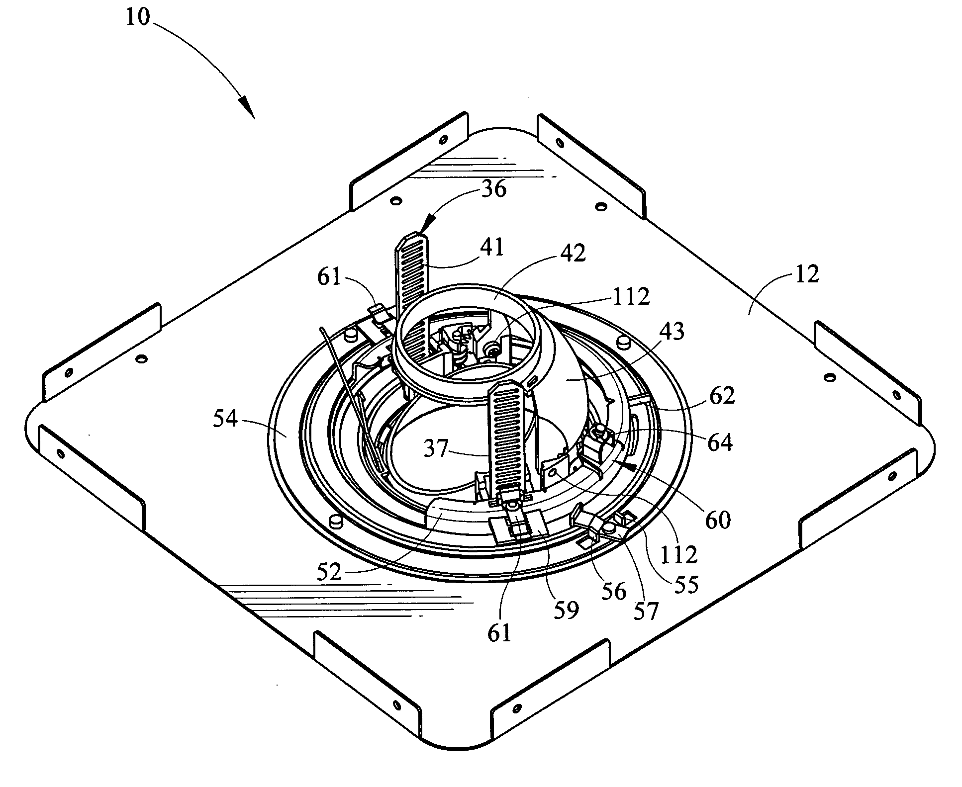
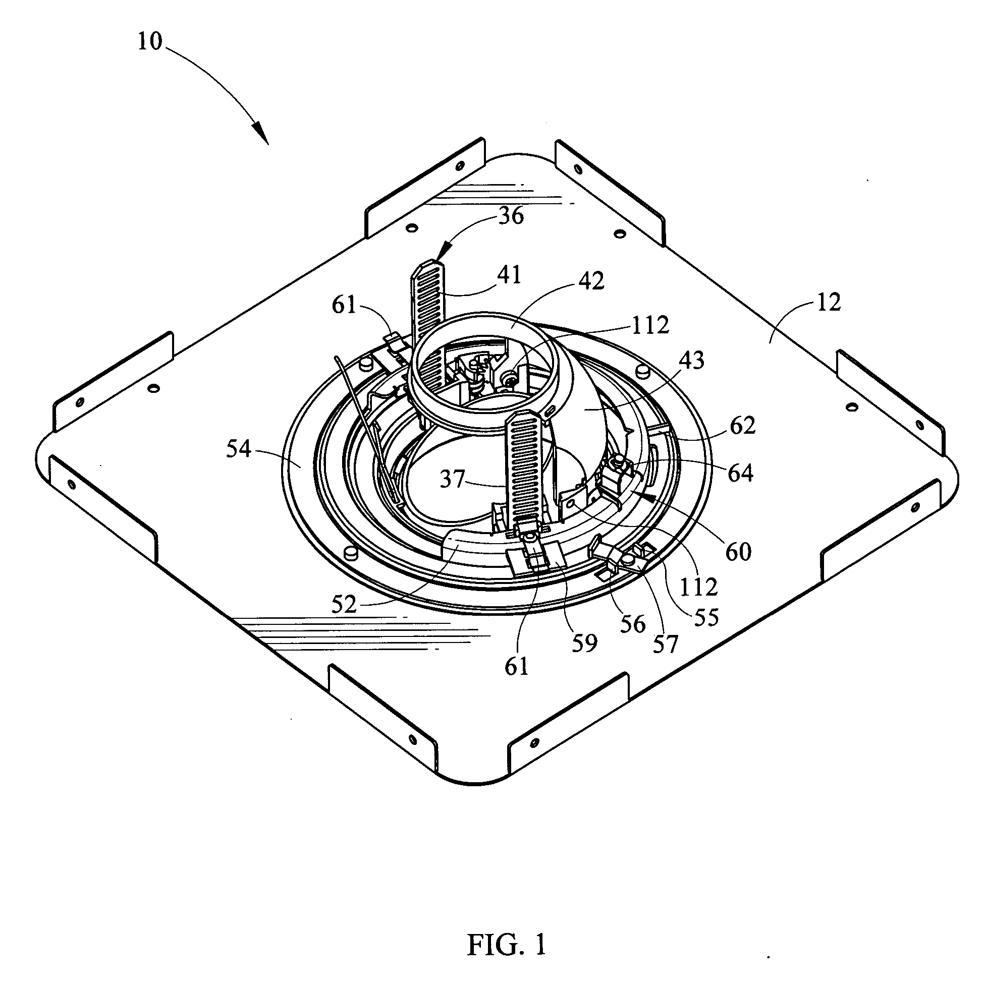
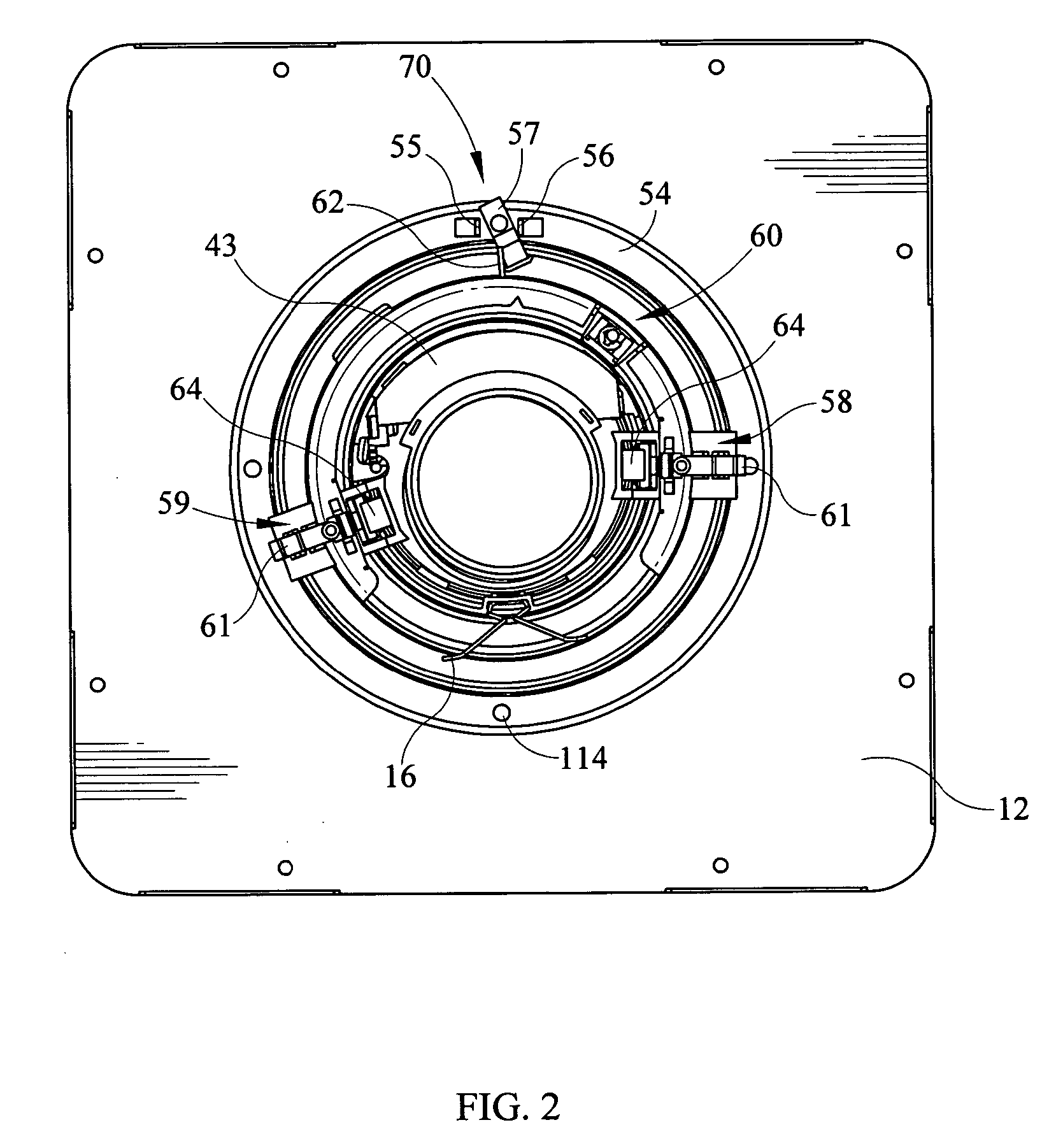
[0031] The recessed fixture with a hinged door and rotatable lamp is generally shown in the figures. FIG. 11 depicts a side sectional view of the assembled fixture 100 wherein a housing 80 surrounds a lamp and other hardware all mounted on a pan 12 for mounting above a ceiling line. As is understood in the art, an aperture is formed in the ceiling line around the plaster ring 111 after the assembled fixture housing and pan 100 is inserted into the rafters or ceiling line. After installation into the ceiling, the drywall is placed around the plaster ring 111 making access to the assembled fixture 100 much more difficult. Hence, with the design of the present recessed fixture with hinged door and rotatable lamp, after installation and affixation of the fixture 100 behind the ceiling and installation of the ceiling, electrical components as well as mechanical and electrical lamp aspects of the fixture may be readily accessed through the aperture formed in the ceiling and through the pl...


PUM


Abstract

A recessed light fixture having a rotation ring allowing rotation of a lamp mounted over the fixture frame aperture, the rotation ring easily rotatable on the frame and held in place by a ring clamp. The recessed light fixture rotation ring has a mechanical brake for locking the ring in place after positioning of the lamp. The ring also has a slip disc positioned between the surface of the frame and the ring to allow easy rotation. The housing of the fixture has junction boxes mounted on side walls which are hinged to the sidewalls of the housing and which swivel into the interior of the housing for ready access after installation through the aperture of the frame. The lamp of the fixture movable about a horizontal adjustment and vertical adjustment axis while also maintaining position with respect to the reflector.

Description

BACKGROUND OF THE INVENTION [0001] The present invention is related to a recessed light fixture which is rotatably adjustable in order to mount a lamp for directing light downwardly or at an angle relative to the vertical axis as well as to a housing structure allowing easy access to the junction boxes after installation of the recessed light fixture. [0002] Various recessed light fixtures are known to allow mounting of the fixture above the ceiling while also providing for rotational adjustment of the light fixture in combination with pivoting of the light fixture about a horizontal axis. See for example U.S. Pat. No. 5,562,343 which allows for rotation of the lamp about a vertical axis up to about 355° while also allowing providing a vertical pivoting mechanism which allows pivoting from about 0° to 45° vertical tilt of the lamp within the lamp holder assembly. These systems allow rotation of the lamp about the horizontal and vertical axis in order that the user may align a light ...

Claims


Application Information

Patent Timeline
IPC IPC(8): F21V15/00
CPCF21V21/30F21S8/02
Inventor CZECH, KENMEYER, RICHARDGAMACHE, THOMASNEELD, JAMES
Owner SIGNIFY NORTH AMERICA CORP
Why Eureka
Try Eureka