Optical integrated unit and optical pickup apparatus including the same

Inactive Publication Date: 2007-01-25
SHARP KK
View PDF17 Cites 0 Cited by
  • Summary
  • Abstract
  • Description
  • Claims
  • Application Information

AI Technical Summary

Benefits of technology

[0038] According to the above-described configuration of the present invention, the adhesive strength of the adhesive agent applied to the prism through which the outgoing light first passes is lower than that of the adhesive agent applied to another prism.
[0039]

Problems solved by technology

However, in the above-described conventional example, since the light dividing section and the light receiving element are adhered to each other via the support substrate, the thickness error of the support substrate and the thickness error of the relay substrate provided between the light receiving element and the support substrate become the length error of the light path.
Therefore, it is impossible to adjust the light receiving element highly accurately.
Further, since the length error of the light path causes the loss of signal, it is impossible to provide a rel

Method used


Image

  • Optical integrated unit and optical pickup apparatus including the same
  • Optical integrated unit and optical pickup apparatus including the same
  • Optical integrated unit and optical pickup apparatus including the same

Examples


Embodiment Construction

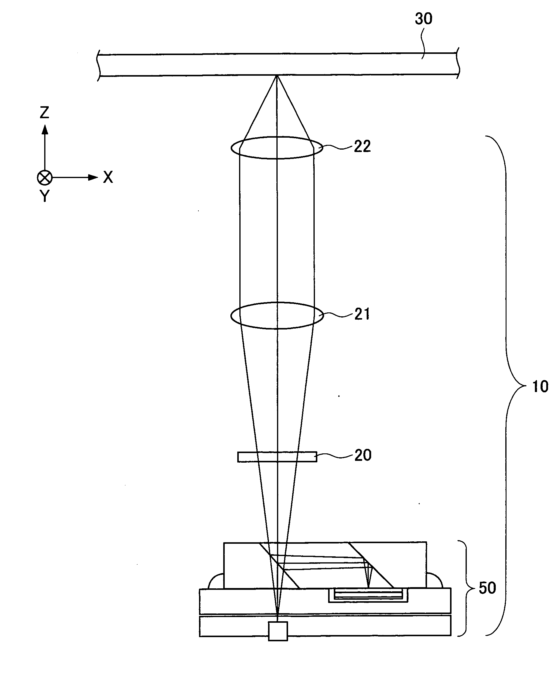
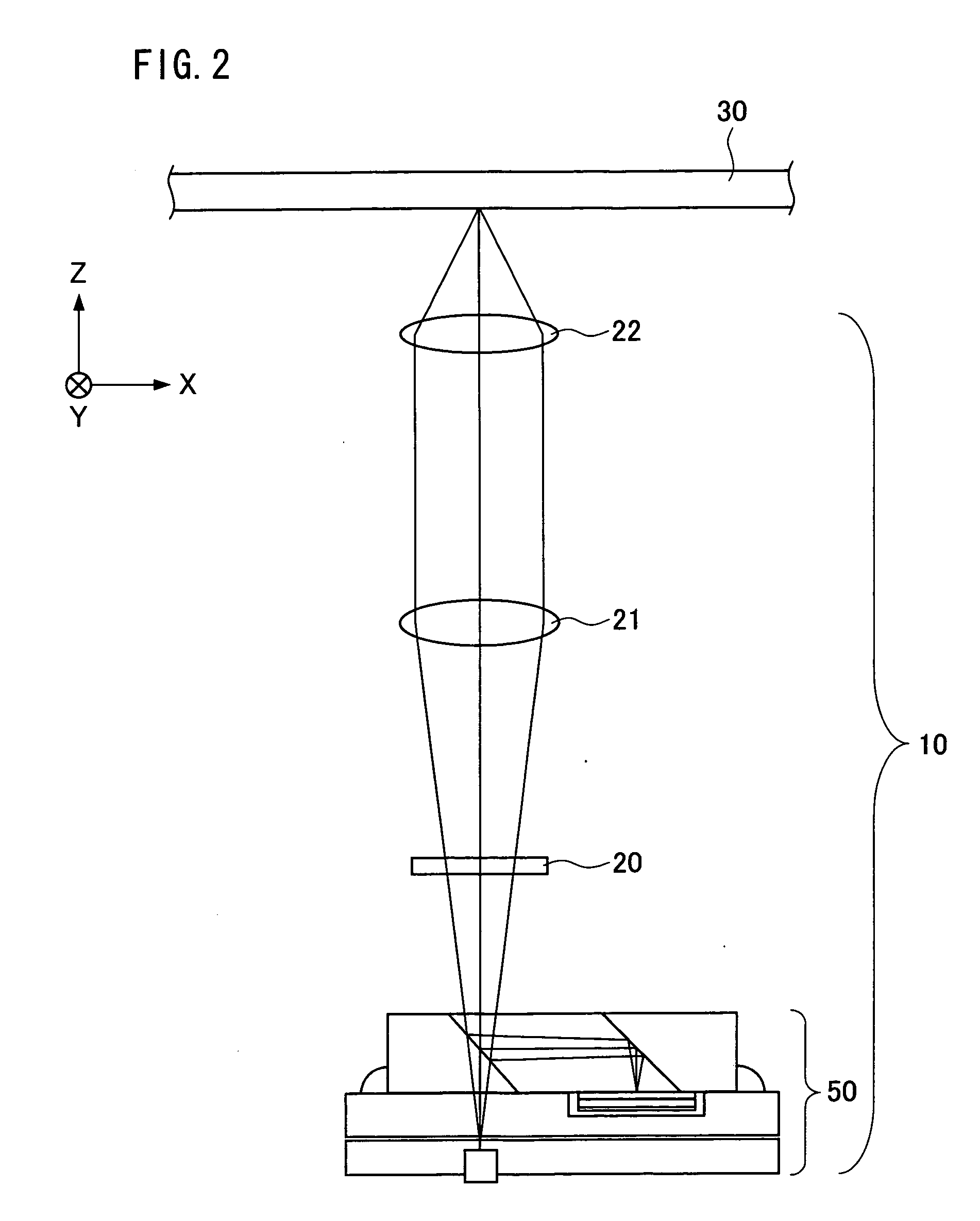
[0075] The following will explain one embodiment of the present invention. Note that the present embodiment will explain an example in which an optical integrated unit of the present invention is used in an optical pickup apparatus included in an optical recording-reproduction apparatus which optically records information to and reproduces information from an optical disc that is an optical recording medium.

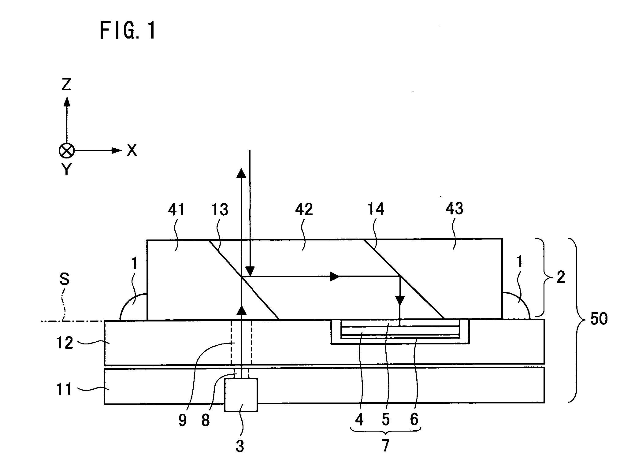
[0076] First, the following configuration can be thought of as a comparative example with respect to the above-described conventional configuration. In the above-described conventional example, since the light dividing section and the light receiving element are adhered to each other via the support substrate, the thickness error of the support substrate and the thickness error of the relay substrate provided between the light receiving element and the support substrate cause the length error of the light path. Therefore, it is impossible to adjust the light receiving element hi...


PUM


Abstract

An optical integrated unit of the present invention includes: a semiconductor laser that is a light source; at least one light receiving element; a light dividing section which divides outgoing light from the semiconductor laser and returning light from an optical disc, and reflects the returning light so as to guide it to the light receiving element; and a support substrate, and a second support substrate is concave, the light dividing section includes at least three prisms, the prisms on both sides of the light dividing section are respectively adhered to two protrusions of the concave second support substrate, and the light receiving element is adhered to the light dividing section via a cover glass. With this, it is possible to solve a problem of a conventional technology, that is, such a problem that the light receiving element cannot be adjusted highly accurately because of the thickness errors of the support substrate and the relay substrate.

Description

[0001] This Nonprovisional application claims priority under 35 U.S.C. § 119(a) on Patent Application No. 141907 / 2005 filed in Japan on May 13, 2005, the entire contents of which are hereby incorporated by reference. FIELD OF THE INVENTION [0002] The present invention relates to (i) an optical integrated unit for realizing miniaturization of an optical pickup apparatus used when recording information to or reproducing information from an information recording medium such as an optical disc, and (ii) an optical pickup apparatus using this optical integrated unit. BACKGROUND OF THE INVENTION [0003] In recent years, it has been strongly desired to (i) increase the density and capacity of the information storage capacity of an optical recording medium, such as an optical disc, in order to record large volumes of information to the optical recording medium and (ii) reduce the size and weight of an optical pickup apparatus in order to improve the mobility of the optical pickup apparatus. ...

Claims


Application Information

Patent Timeline
IPC IPC(8): G11B7/135
CPCG11B7/1356G11B7/1205G11B7/123
Inventor KANAZAWA, YASUNORI
Owner SHARP KK
Why Eureka
Try Eureka