

Liquid jetting head, method for changing protective tape in adhesive strength, and protective tape
- Summary
- Abstract
- Description
- Claims
- Application Information
AI Technical Summary
Benefits of technology
Problems solved by technology
Method used
Image

Examples
embodiment 1
[0021]Hereinafter, the preferred embodiments of the present invention will be described in detail with reference to the appended drawings. First, the first preferred embodiment of the present invention will be described with reference to FIGS. 1-4.
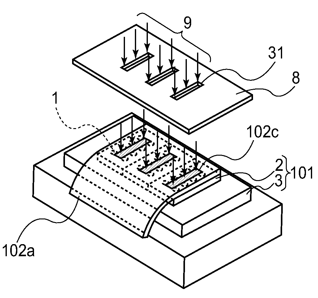
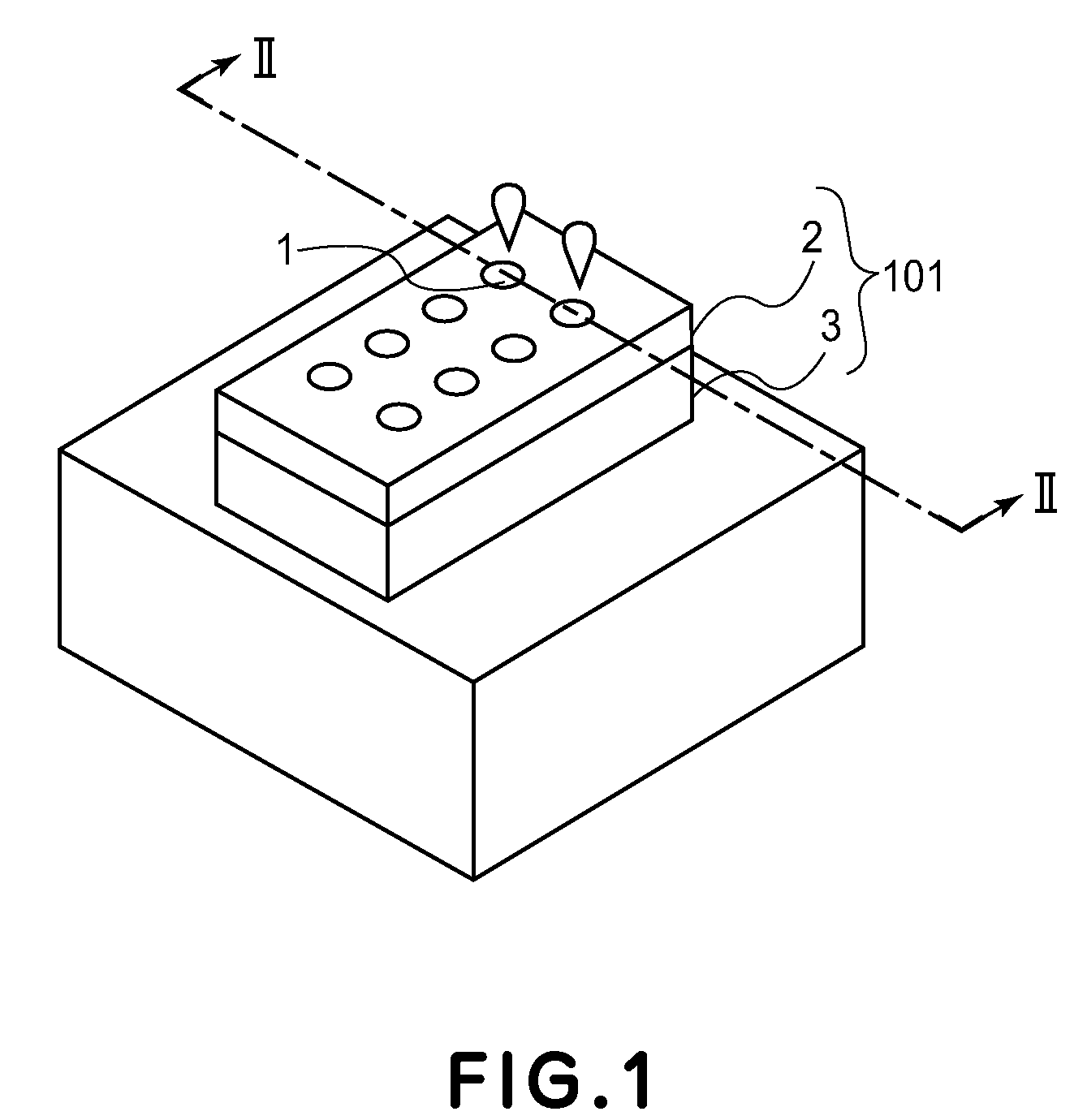
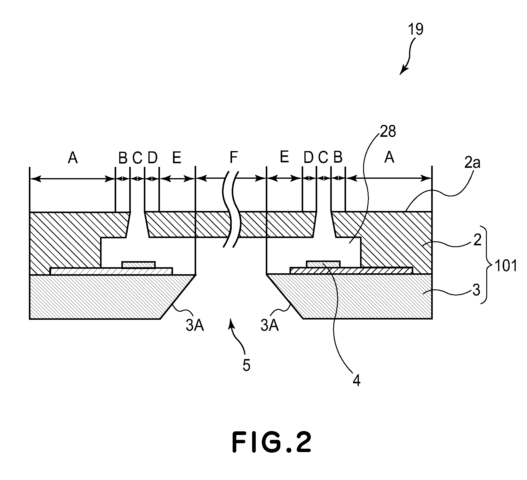
[0022]FIGS. 1-4 are drawings of one of the typical recording apparatuses to which the present invention is applicable. FIGS. 1-4 were schematically drawn for describing the present invention; the number of ink jetting orifices or the like is different from that of the actual recording head. FIG. 1 is a schematic perspective view of the recording head 101 (liquid jetting head), and FIG. 2 is an enlarged sectional view of the ink jetting orifices of the recording head 101 in FIG. 1, and their adjacencies, at Line II-II in FIG. 1.
[0023]Referring to FIGS. 1 and 2, the ink jet recording head 101 in this embodiment has a silicon substrate 3, and a top plate 2 which is on the silicon substrate 3. It has a common liquid chamber 5, which is a hollo...
embodiment 2
[0037]FIG. 5 is a drawing which depicts the second embodiment of the present invention. FIG. 5(a) is a perspective view of a mask 35, a protective tape 103, and a recording head 101. The protective tape 103, in this embodiment, is pasted to the surface of the recording head 101, which has the openings of the ink jetting orifices of the recording head 101. FIG. 5(b) is a perspective view of the recording head 101 and the protective tape 103 on the recording head, in which the liquid jetting orifices, and their adjacencies, were exaggerated to clearly show the distinction between the portion 103b of the protective tape 103, which is greater in adhesive strength, and the portions 103a of the protective tape 103, which are less in adhesive strength. FIG. 5(c) is a perspective view of the recording head 101, and how the recording head 101 appears after the peeling of the protective tape 103.
[0038]The protective tape 103 in this embodiment is pasted to the recording head 101 using the fol...
embodiment 3
[0044]FIG. 6 is a drawing which depicts the third embodiment of the present invention. FIG. 6(a) is a perspective view of the mask 37, protective tape 105, and recording head 106. The protective tape 105 is pasted to the surface of the recording head 106, which has the openings of the liquid jetting orifices. FIG. 6(b) is a perspective view of the recording head 106 and the protective tape 105 on the recording head, in which the liquid jetting orifices, and their adjacencies, were exaggerated to clearly show the distinction between the portion 105a of the protective tape 105, that is, the portion next to the liquid jetting orifices, which is greater in adhesive strength, and the portions 105b of the protective tape 103, that is, the rest, which are less in adhesive strength. FIG. 6(c) is a perspective view of the recording head 106, and how the recording head 106 appears after the peeling of the protective tape 105.
[0045]The protective tape 105 in this embodiment is pasted to the re...
PUM
 Abstract
Description
Claims
Application Information