Illumination device, image display device, and projector

Active Publication Date: 2007-01-25
SEIKO EPSON CORP
View PDF5 Cites 55 Cited by
  • Summary
  • Abstract
  • Description
  • Claims
  • Application Information

AI Technical Summary

Benefits of technology

[0097] According to the invention, increases in the size and complexity of the device

Problems solved by technology

When using a predetermined optical system to realize uniform illuminance distribution, there is concern that a desired image may not be obtained due to the positional relationship between the laser light and the optical system.
Furthermore, depending on the conf

Method used


Image

  • Illumination device, image display device, and projector
  • Illumination device, image display device, and projector
  • Illumination device, image display device, and projector

Examples


first embodiment

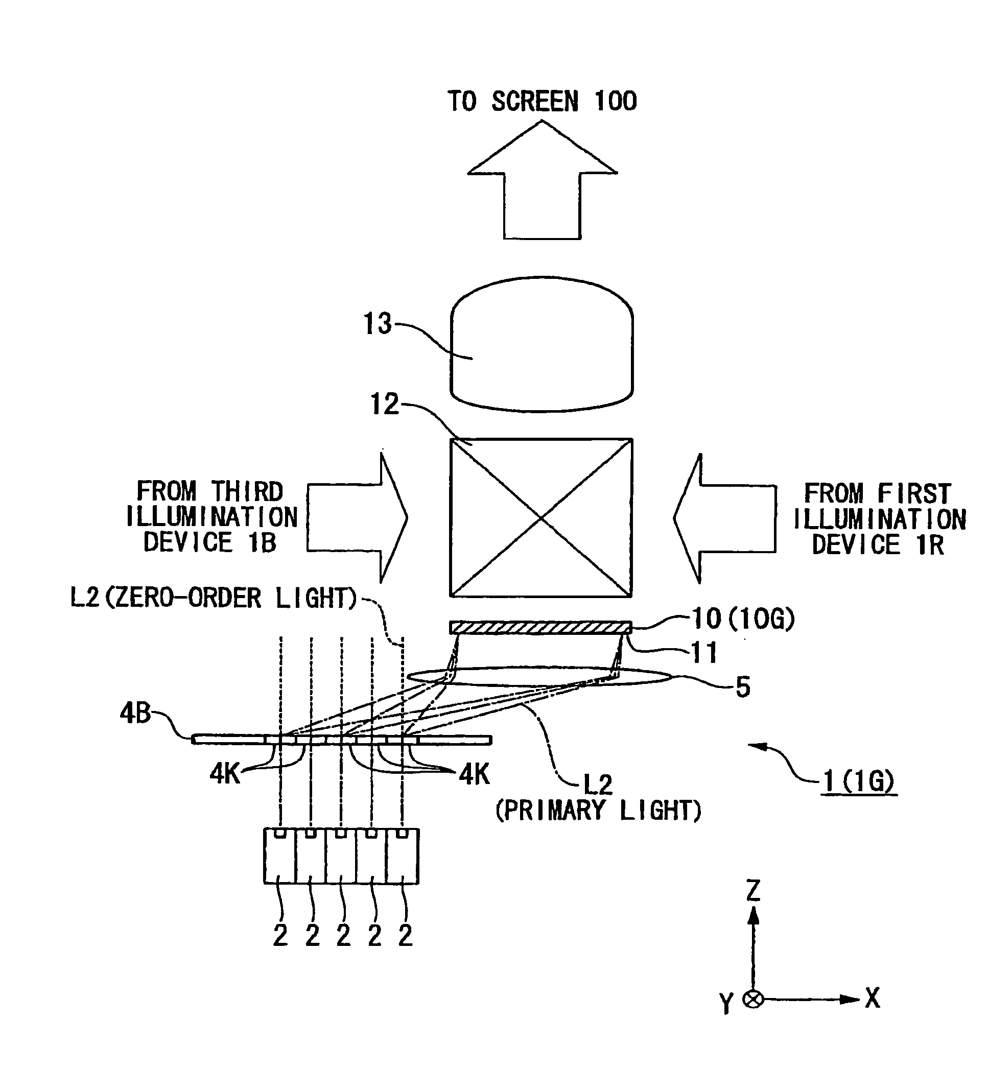
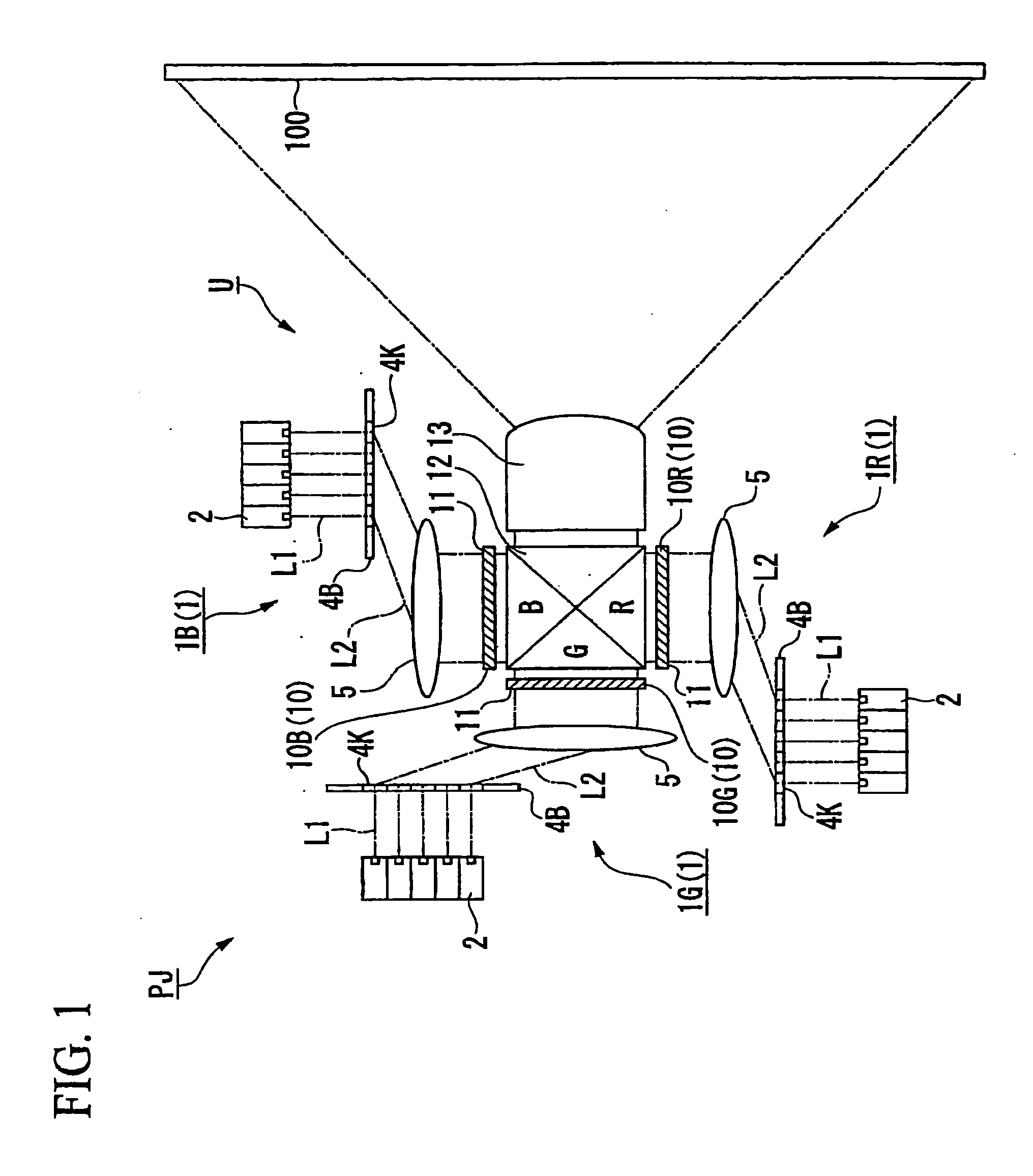
[0133] A first embodiment will be explained. FIG. 1 is a schematic diagram of an image display device PJ according to a first embodiment, and FIG. 2 is an enlarged view of primary parts of FIG. 1.

[0134] In this embodiment, as an example of an image display device, a projection type image display device (projector) is described. This projection type image display device projects colored light containing image information generated by a spatial light modulation device via a projection system on a screen.

[0135] In FIG. 1, the projector PJ includes a projection unit U which projects light containing image information on a screen 100 (second face).

[0136] By projecting the light from the projection unit U on the screen 100, an image is formed on the screen 100.

[0137] The projector PJ of this embodiment uses a transmission type screen as the screen 100, and projects the light containing image information on the screen 100 from a front face side thereof.

[0138] The projection unit U inc...

second embodiment

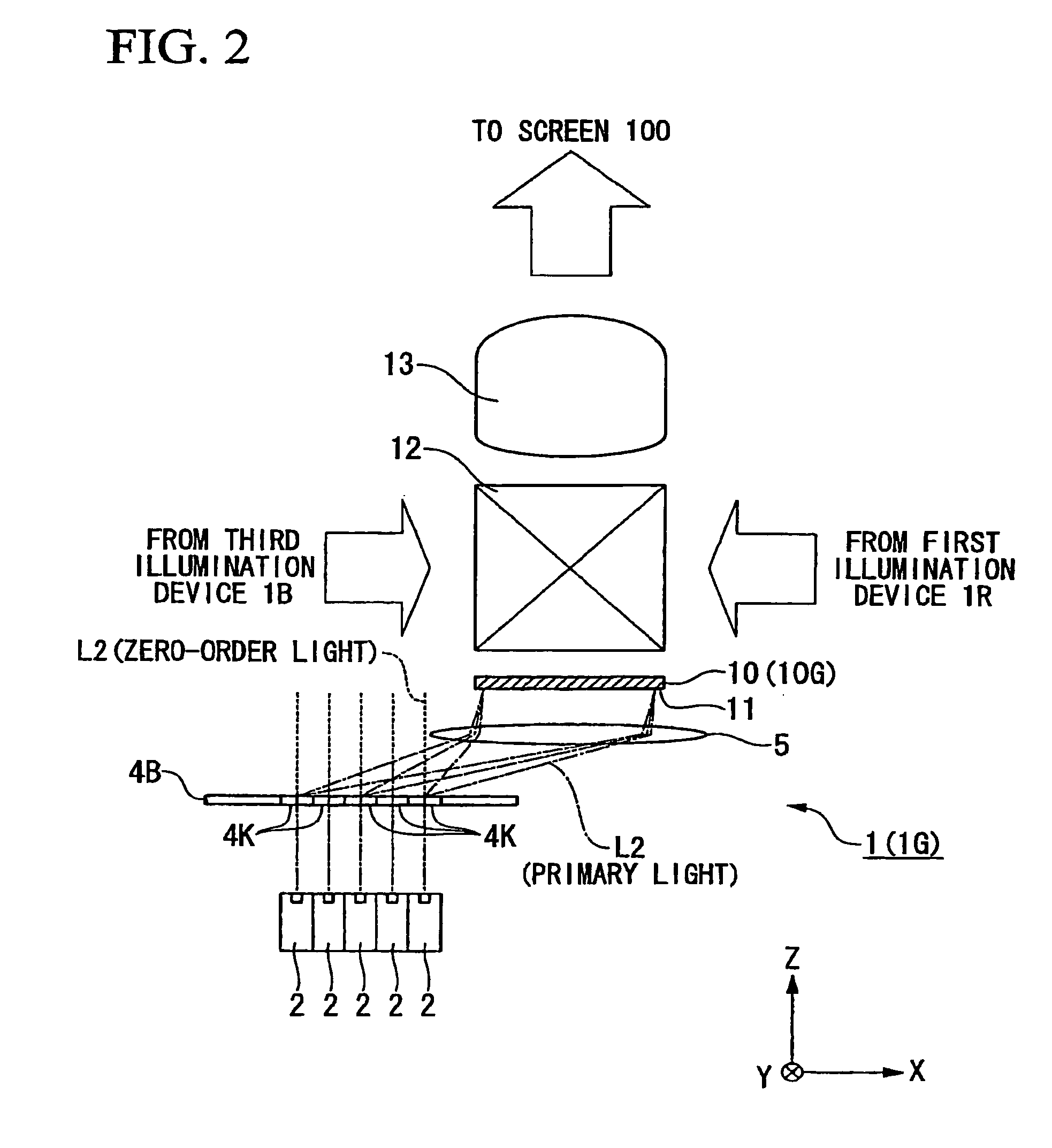
[0251] A second embodiment will be explained while referring to FIG. 7.

[0252] In the following explanation, constituent parts which are identical or similar to those of the preceding embodiment are designated with identical reference numerals, and explanation thereof is simplified or omitted.

[0253] While in the embodiment of FIG. 2 described above, the surface (light-emitting face) of the diffractive optical element 4K and the incidence face 11 of the spatial light modulation device 10 are arranged substantially in parallel, as shown in FIG. 7, the surface (light-emitting face) of the diffractive optical element 4K and the incidence face 11 of the spatial light modulation device 10 may be arranged such that they face in mutually different directions. It is possible to make the device smaller.

third embodiment

[0254] Subsequently, a third embodiment will be explained while referring to FIG. 8.

[0255]FIG. 8 is a schematic plan view showing the positional relationship between a spatial light modulation device 10 (incidence face 11) and a plurality of laser light source devices 2.

[0256] As shown in FIG. 8, the incidence face 11 has a substantially rectangular (elongated) shape in plan view, having a first side H1 parallel to the Y axis and a second side H2 parallel to the X axis.

[0257] Incidentally, “plan view” signifies the shape and positional relationship in a two-dimensional direction along a face.

[0258] Thus, the plan view represents the shape and positional relationship in a two-dimensional direction along one face.

[0259] Therefore, for example, “the incidence face 11 is substantially rectangular in plan view” signifies that the incidence face 11 is substantially rectangular in a two-dimensional direction

[0260] The second side H2 is longer than the first side H1.

[0261] The light-...


PUM


Abstract

An image display device includes: a first face; a laser light source device emitting laser light; and a diffractive optical element on which the laser light emitted from the laser light source device is incident, generating diffracted light from the incident laser light, and illuminating the first face with the diffracted light, the first face is provided at a position on which zero-order light emitted from the diffractive optical element is not incident, and an image is displayed by light via the first face.

Description

CROSS-REFERENCE TO RELATED APPLICATION [0001] This application claims priority on Japanese Patent Application No. 2005-217148, filed Jul. 27, 2005, Japanese Patent Application No.2005-286993, filed Sep. 30, 2005, Japanese Patent Application No. 2005-213493, filed Jul. 22, 2005, and Japanese Patent Application No.2005-213495, filed Jul. 22, 2005, the contents of which are incorporated herein by reference. BACKGROUND [0002] 1. Technical Field [0003] The present invention relates to an illumination device, an image display device, and a projector. [0004] 2. Related Art [0005] Projection type image display devices (projectors) are conventionally known. [0006] A projection type image display device uses a projection system to project colored light, which contains image information generated by a spatial light modulation device such as a liquid crystal device, onto a screen. [0007] In a projection type image display device, as disclosed in Japanese Unexamined Patent Publication, First Pub...

Claims


Application Information

Patent Timeline
IPC IPC(8): G02B6/34
CPCG02B27/1046G02B27/1093G02B27/141H04N9/315G02B27/42G02B27/4244G02B27/425G02B27/149
Inventor YAMAUCHI, TAISUKETAKEDA, TAKASHI
Owner SEIKO EPSON CORP
Why Eureka
Try Eureka