Control apparatus of vehicular automatic transmission

a technology of automatic transmission and control apparatus, which is applied in mechanical devices, transportation and packaging, and gearing. it can solve problems such as uncomfortable behavior of vehicles, downshifting two or more stages, and vehicle discomfor

Inactive Publication Date: 2007-01-25
TOYOTA JIDOSHA KK
View PDF4 Cites 14 Cited by
  • Summary
  • Abstract
  • Description
  • Claims
  • Application Information

AI Technical Summary

Benefits of technology

[0010] In a vehicular automatic transmission in which a plurality of speed change stages of different speed change ratios are established by either one of an event of simultaneous engagements of two friction engagement devices belonging to the first group and an event of simultaneous engagements of one of the friction engagement devices belonging to the first group and one of the friction engagement devices belonging to the second group, the above-described hydraulic control apparatus of the vehicular automatic transmission operates as described below if there occurs a failure where an oil pressure that causes simultaneous engagements of friction engagement devices belonging to the second group is output. That is, on the basis of the state of engagement of at least one friction engagement device belonging to the first group, the switching device changes the manner in which oil pressures for engaging friction engagement devices belonging to the second group are input to the fail-safe device which stops the supply of an oil pressure to a fri

Problems solved by technology

On that occasion, an automatic transmission having multiple speed change stages with an increased number of friction engagement devices may sometimes undergo a downshift of two or more stages from the speed change stage maintained immediately prior to the occurrence of the failure, in which case there is a possibility of occurrence of an uncomfortable behavior of the vehicle.
Then, at the time of a failure where the oil pressure for engagement of the clutch C4 is output during running with the eighth speed change stage, the clutch C4 is engaged with priority over the brake B1, to establish the sixth speed change stage, thus bringing about a downshif

Method used


Image

  • Control apparatus of vehicular automatic transmission
  • Control apparatus of vehicular automatic transmission
  • Control apparatus of vehicular automatic transmission

Examples


Embodiment Construction

[0025] In the following description and the accompanying drawings, the present invention will be described in more detail with reference to exemplary embodiments.

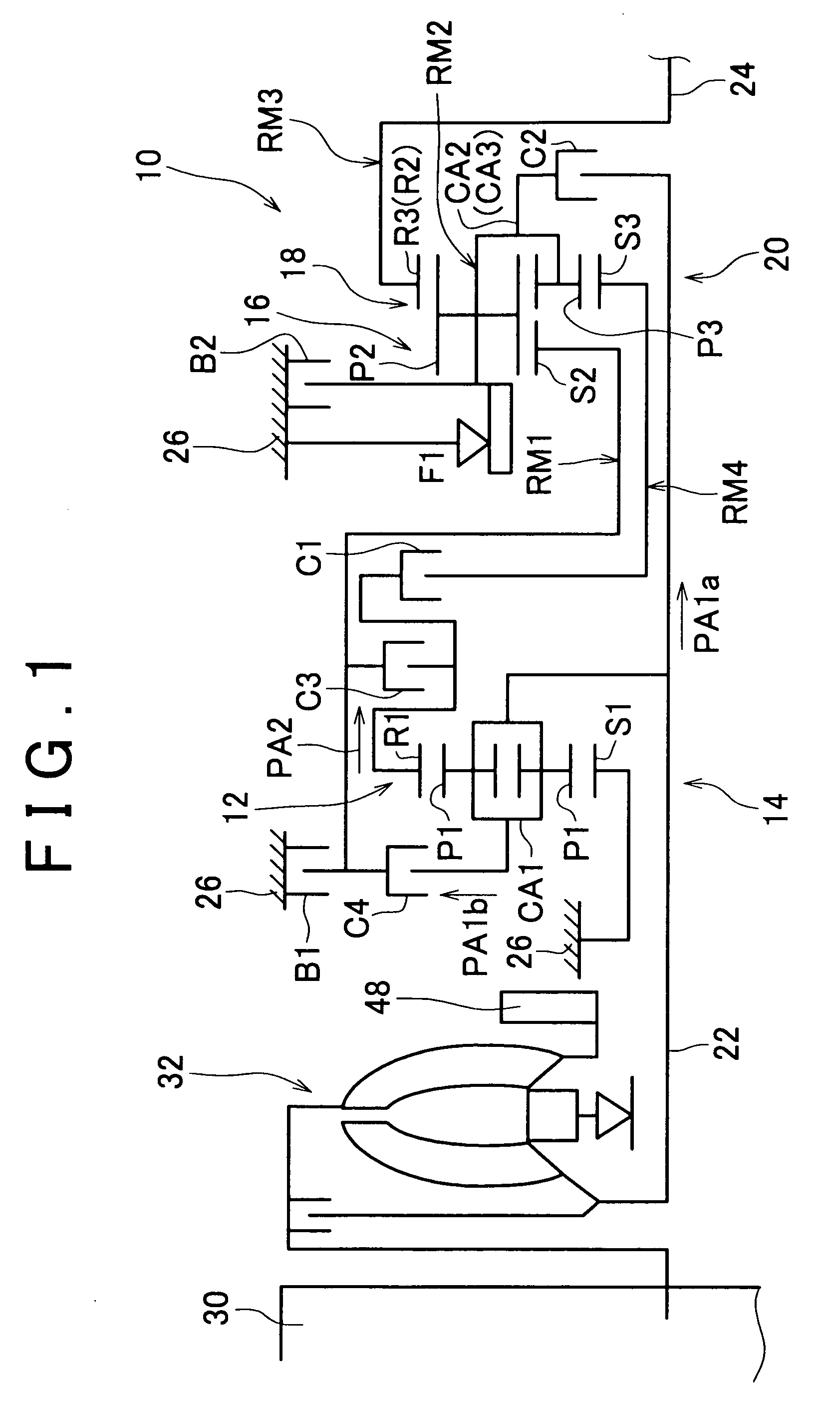
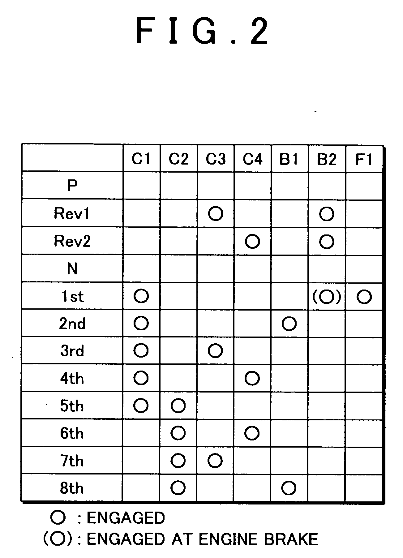
[0026]FIG. 1 is a skeleton diagram illustrating a construction of a vehicular automatic transmission (hereinafter, referred to as “automatic transmission”) 10 to which the present invention is applied. FIG. 2 is an operation chart (engagement operation table) illustrating combinations of operations of engagement devices (engagement elements) for establishing a plurality of speed change stages in the automatic transmission 10 shown. The automatic transmission 10 has, in a transmission case (hereinafter, referred to as “case”) 26 provided as a non-rotating member attached to a vehicle body, a first speed changer portion 14 made up mainly of a double pinion-type first planetary gear set 12, and a second speed changer portion 20 made up mainly of a single pinion-type second planetary gear set 16 and a double pinion-type third ...


PUM


Abstract

At the time of a failure in the second group of engagement devices, the manner of input of oil pressures to a fail-safe valve group is changed via a priority degree switching valve on the basis of the state of engagement of engagement devices of the first group in such a manner that the predetermined degrees of priority for the supply of one of oil pressures PC4, PB1 output from linear solenoid valves SL4, SL5 to a corresponding one of a clutch C4 and a brake B1 via the fail-safe valve group are changed so as to avoid an event that the fail-safe gear stage established in order to prevent the occurrence of interlock of the automatic transmission involves a downshift of two or more stages from the speed change stage maintained immediately prior to the occurrence of the failure. Therefore, it is possible to prevent the occurrence of an uncomfortable behavior of the vehicle caused by the shift to the fail-safe gear stage.

Description

INCORPORATION BY REFERENCE [0001] The disclosure of Japanese Patent Applications No. 2005-212873 filed on Jul. 22, 2005, including the specification, drawings and abstract is incorporated herein by reference in its entirety. BACKGROUND OF THE INVENTION [0002] 1. Field of the Invention [0003] The present invention relates to a hydraulic control apparatus of a vehicular automatic transmission and, more particularly, to a fail-safe apparatus that avoids the occurrence of interlock of an automatic transmission. [0004] 2. Description of the Related Art [0005] Vehicles provided with an automatic transmission that includes a plurality of friction engagement devices belonging to a first group, and a plurality of friction engagement devices belonging to a second group, and that establishes a plurality of speed change stages of different speed change ratios by simultaneous engagements of one of the friction engagement devices belonging to the first group and of one of the friction engagement ...

Claims


Application Information

Patent Timeline
IPC IPC(8): F16H31/00F16H59/68F16H61/00F16H61/12F16H61/68F16H61/684F16H61/686
CPCF16H3/663F16H61/12F16H61/686F16H2061/1232F16H2200/006Y10T477/6934F16H2200/2007F16H2200/2023F16H2200/2046F16H2061/1264Y10S477/906F16H2200/0086F16H61/4192F16H61/00
Inventor NOZAKI, KAZUTOSHIHONDA, ATSUSHIABE, AKIHARUOTA, HIROFUMI
Owner TOYOTA JIDOSHA KK
Why Eureka
Try Eureka