Method and device for epicardial ablation

a technology of epicardial ablation and cryotherapy, which is applied in the field of diagnosis and treatment of heart and vascular tissue, can solve the problems of absolute procedure, no correction of mapping errors, and the potential of destroying healthy coronary structures

Inactive Publication Date: 2007-01-25
MEDTRONIC CRYOCATH LP
View PDF27 Cites 59 Cited by
  • Summary
  • Abstract
  • Description
  • Claims
  • Application Information

AI Technical Summary

Problems solved by technology

While effective in treating AF, this procedure is complicated to perform, highly invasive, and typically associated with bleeding complications resulting in extended hospitalization.
Presently, radio frequency (RF) energy is a popular method for ablation; but it has the potential of destroying healthy coronary structures and creating stenosis when a lesion is created on an artery or vein.
Another drawback to the use of RF is that once a physician commences to burn the subject tissue, the procedure is absolute.
No correction is made for mapping errors, nor does it allow for continuous or “progressive” monitoring of the ablation process.
Known ablation tools do not allow for enhanced mapping in conjunction with, and as an integral part of, the ablation process.

Method used


Image

  • Method and device for epicardial ablation
  • Method and device for epicardial ablation
  • Method and device for epicardial ablation

Examples


Embodiment Construction

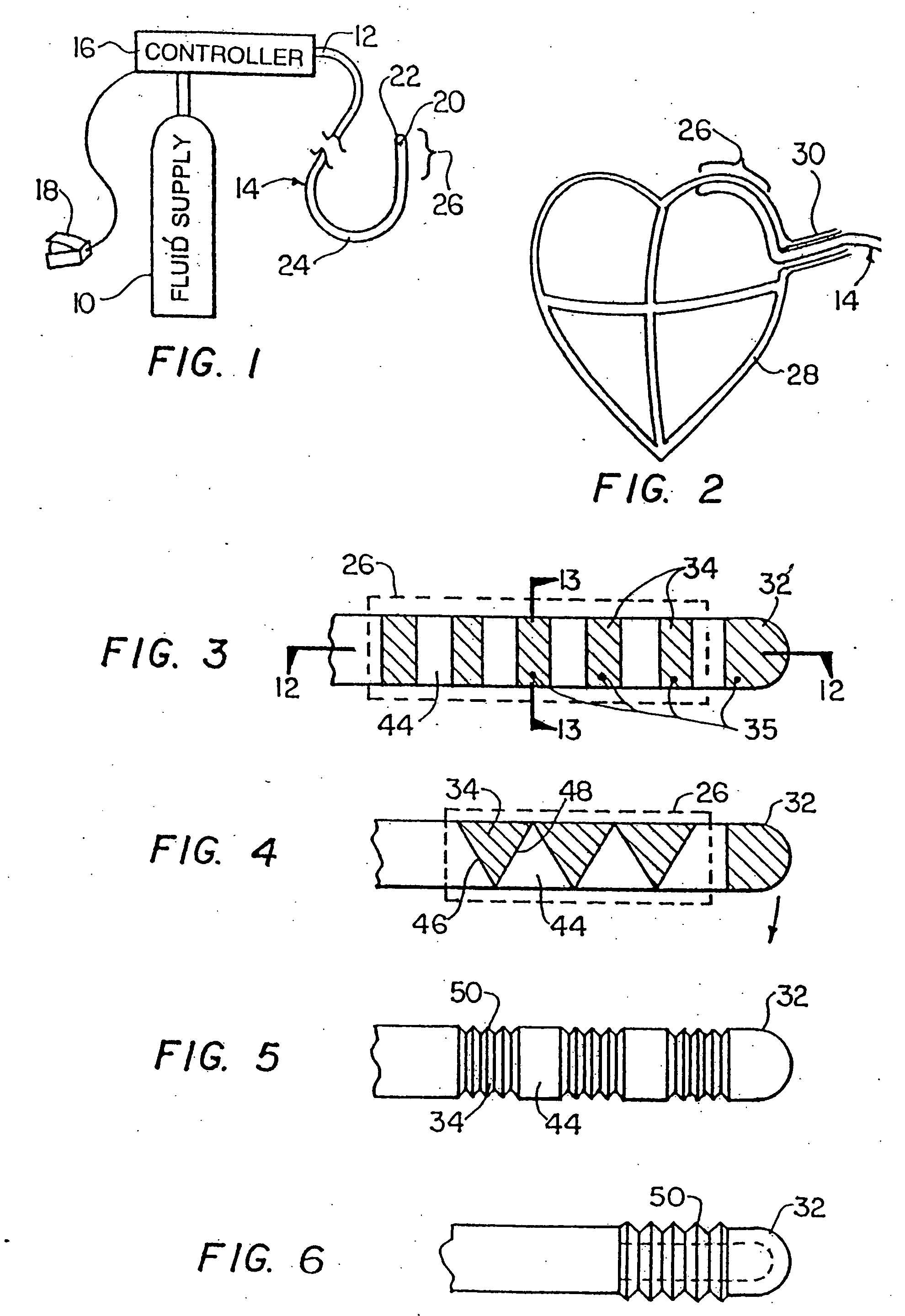
[0060]FIG. 1 is a schematic illustration of a cryosurgical system in accordance with the invention. The system includes a supply of cryogenic or cooling fluid 10 in communication with the proximal end 12 of a flexible catheter 14. A fluid controller 16 is interposed or in-line between the cryogenic fluid supply 10 and the catheter 14 for regulating the flow of cryogenic fluid into the catheter in response to a controller command. Controller commands can include programmed instructions, sensor signals, and manual user input. For example, the fluid controller 16 can be programmed or configured to increase and decrease the pressure of the fluid by predetermined pressure increments over predetermined time intervals. In another exemplary embodiment, the fluid controller 16 can be responsive to input from a foot pedal 18 to permit flow of the cryogenic fluid into the catheter 14. One or more temperature sensors 20 in electrical communication with the controller 16 can be provided to regul...


PUM


Abstract

A method is disclosed for treating heart and vascular tissue with cryotreatment. A medical instrument, such as a catheter is positioned to contact a target region of cardiac tissue such as the epicardial tissue. The instrument or catheter provided includes a cryotreatment element that has thermally-transmissive properties. The cryotreatment element may be a cryochamber for enclosing the flow of a fluid refrigerant therein. The cryotreatment element is disposed at the situs of heart or vascular tissue to be treated, usually by piercing the epicardium sac via an opening in the patient's body. A refrigerant flow within the cryochamber creates endothermic cooling with respect to the targeted heart or vascular tissue, inducing hypothermia and forming iceballs proximate the tissue. The cooling may be reversible and non-permanent, or may be permanent leading to cell death, necrosis, apoptosis and / or surgical excision or ablation of tissue.

Description

CROSS-REFERENCE TO RELATED APPLICATION [0001] This application is related to and claims priority to U.S. Provisional Patent Application Ser. No. 60 / 486,490, filed May 6, 2003, entitled METHOD AND DEVICE FOR EPICARDIAL ABLATION, and is a continuation-in-part of pending Application Serial No. 10 / 10 / 19657,922, filed Sep. 9, 2003, entitled CRYOSURGICAL CATHETER, which is a continuation of application Ser. No. 09 / 845,535, filed Apr. 30, 2001, entitled CRYOSURGICAL CATHETER, now issued U.S. Pat. No. 6,629,972, which application is a continuation of U.S. patent application Ser. No. 09 / 201,071, filed Nov. 30, 1998, now issued U.S. Pat. No. 6,235,019, which is a continuation-in-part of U.S. patent application Ser. No. 08 / 893,825, filed Jul. 11, 1997, now issued U.S. Pat. No. 5,899,899, which is a continuation-in-part of U.S. patent application Ser. No. 08 / 807,382, filed Feb. 27, 1997, now U.S. Pat. No. 5,899,898, the entirety of all of which is incorporated herein by reference.STATEMENT REGA...

Claims


Application Information

Patent Timeline
Patent Type & Authority Applications(United States)
IPC IPC(8): A61B18/02
CPCA61B18/02
Inventor ABBOUD, MARWANWITTENBERGER, DANNAHON, DANIELARLESS, STEVEN G.
Owner MEDTRONIC CRYOCATH LP
Why Eureka
Try Eureka