
Underground pipe for transporting fuel and a method of fabricating it

a technology for transporting fuel and underground pipes, which is applied in the direction of flexible pipes, applications, coatings, etc., can solve the problems of large on-site pollution, and the polymer tube construction that has been used until now no longer meets the specification ul971 and other problems, to achieve the effect of limiting the flexibility of the pipe and small thickness

Inactive Publication Date: 2007-02-01
NOBEL PLASTIQUES
View PDF23 Cites 12 Cited by
  • Summary
  • Abstract
  • Description
  • Claims
  • Application Information

AI Technical Summary

Benefits of technology

[0013] The invention relates to a flexible pipe structure that is compatible with the above-specified standard, serving in particular to provide very low levels of permeability or of dimensional change, so as to obtain a pipe that is cleaner and more reliable.
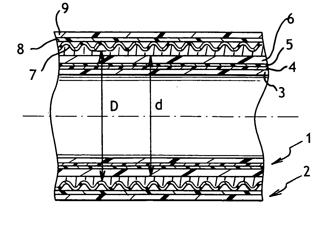
[0015] Thus, the space for retaining any fuel that escapes from the inner tube is defined by the corrugations whose helical shape makes it possible to remove that fuel along the pipe when the quantity thereof is excessive. The absence of bonding between the inner and outer tubes also makes it possible to limit the consequences of expansion of the pipe on connectors connecting the pipe to elements of the circuit in which it is included: when the outer tube expands, the corrugations come closer together so the force exerted by the outer tube on the connectors is limited. It is thus possible to ensure that the outer tube exerts a force on the connectors that is equivalent to the force that would be caused by elongation of less than only about 0.2%.
[0017] The lack of bonding between the inner and outer tubes is thus obtained simply, and it is easier to cause any fuel that has leaked from the inner tube to flow along the pipe.
[0024] The tape serves to avoid the material of the outer layer filling the corrugations at the exit from the die, which would otherwise limit the flexibility of the pipe. It is then possible to have an outer layer of relatively small thickness.

Problems solved by technology

With recent changes in environmental standards, the polymer tube constructions that have been used until now no longer satisfy Specification UL971.
This criterion is important since numerous instances have been reported in which by shrinking or lengthening due to aging, the tube has caused connectors to rupture, thereby leading to large amounts of on-site pollution.

Method used


Image

  • Underground pipe for transporting fuel and a method of fabricating it
  • Underground pipe for transporting fuel and a method of fabricating it

Examples


Embodiment Construction

[0029] With reference to FIG. 1, the pipe in accordance with the invention comprises an inner tube given overall reference 1, and an outer tube given overall reference 2. The inner tube 1 and the outer tube 2 are coaxial.

[0030] The inner tube 1 comprises, from the inside towards the outside: an inner layer 3, a taped intermediate layer 4, mechanical reinforcement 5, and an outer layer 6.

[0031] The inner layer 1 is made of polyamide, preferably polyamide 12 (PA12). Because of the desired flexibility, it is preferable to use a plasticized grade, typically plasticized to 12.5%. The thickness of the inner layer lies, for example, in the range 1 millimeter (mm) to 3 mm, depending on diameter.

[0032] The intermediate layer 4 is made of an aluminum-coated polyester tape. Typically the tape is made up of two polyester layers having a thickness of a few micrometers (usually 24 micrometers (μm)) sandwiching an aluminum strip having thickness lying in the range 30 μm to 60 μm. This tape is p...


PUM

PropertyMeasurementUnit
diametersaaaaaaaaaa
elongationaaaaaaaaaa
thicknessaaaaaaaaaa

Abstract

The present invention relates to a pipe for transporting fuel, the pipe comprising an inner tube and an outer tube that are coaxial with a space being maintained between them by spacer means, the outer tube comprising an outer layer and an inner layer, the inner layer being helically corrugated and free relative to the inner tube so as to form the spacer means. The invention also provides a method of fabricating said pipe.

Description

[0001] The present invention relates to an underground pipe for transporting fuel. The invention also relates to a method of fabricating such a pipe. BACKGROUND OF THE INVENTION [0002] Fuel is distributed to users by means of service stations installed along roads for automobile activities, in ports for maritime activities, or in depots for aviation and domestic applications. [0003] A service station generally comprises storage tanks including one or more distribution pumps, and a zone that is for receiving the vehicle and that is fitted with delivery pumps. [0004] The functions of the distribution pumps are to supply fuel to the delivery pumps and to mix fuels so as to obtain a desired octane rating. In particular, in the United States, three grades of gasoline are available at the pump (96, 97, and 98 octane), but stations only have two tanks (96 and 98), with the third grade of gasoline being obtained by a 50 / 50 mixture of the other two grades of gasoline. Thus, there is no direc...

Claims


Application Information

Patent Timeline
Patent Type & Authority Applications(United States)
IPC IPC(8): F16L11/00
CPCB29C47/0023B29C47/021B29C47/023B29C59/021B29C63/105B29D23/001B29K2021/003B29K2023/00B29K2023/06B29K2027/12B29K2067/00B29K2075/00B29K2077/00B29K2105/0827B29K2105/0836B29K2267/00B29K2277/00B29K2277/10B29K2305/02B29L2009/00B29L2023/005F16L11/15F16L11/20B29C47/0033B29C48/09B29C48/13B29C48/151B29C48/153
Inventor MILHAS, PIERRE
Owner NOBEL PLASTIQUES
Learn More