Diaphragm for micro-electroacoustic device

a micro-electroacoustic and diaphragm technology, applied in the direction of fiber diaphragms, transducer diaphragms, instruments, etc., can solve the problem of limited space available for loudspeakers in mobile phones, and achieve the effect of reducing the maximum deformation displacement of the diaphragm, increasing the rigidity of the diaphragm, and reducing the spa

Inactive Publication Date: 2007-02-01
HON HAI PRECISION IND CO LTD
View PDF7 Cites 11 Cited by
  • Summary
  • Abstract
  • Description
  • Claims
  • Application Information

AI Technical Summary

Benefits of technology

[0005] A diaphragm for a micro-electroacoustic transducer in accordance with a preferred embodiment of the present invention comprises a first layer including an exposed region and a covered region. A second layer overlaps the covered region of the first layer to thereby increase the rigidity of the diaphragm. The maximum deformation displacement of the diaphragm is accordingly reduced compared with conventional diaphragms when undergoing a same power (force). Thus, loudspeakers fitted with the diaphragms of the present invention occupy a smaller space than loudspeakers with conventional diaphragms while can have the same power output. Understandably and alternatively, loudspeakers fitted with the diaphragms of the present invention and occupying the same amount of space as loudspeakers fitted with conventional diaphragms can undergo larger amounts of power input (force) and can have larger power output. This is due to the rigidity of the diaphragm in the present invention being larger than that of the conventional diaphragm.

Problems solved by technology

As design style for mobile phones emphasizes lightness, thinness, shortness, smallness, energy-efficiency, low cost, the space available for loudspeakers within mobile phones is therefore limited.

Method used


Image

  • Diaphragm for micro-electroacoustic device
  • Diaphragm for micro-electroacoustic device
  • Diaphragm for micro-electroacoustic device

Examples


first embodiment

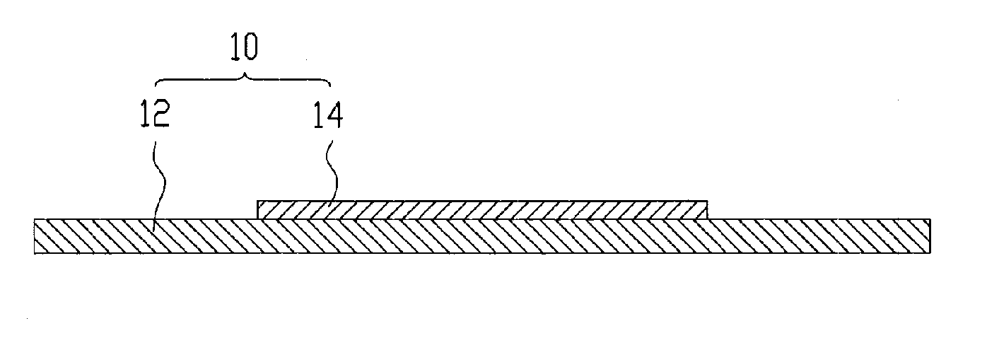
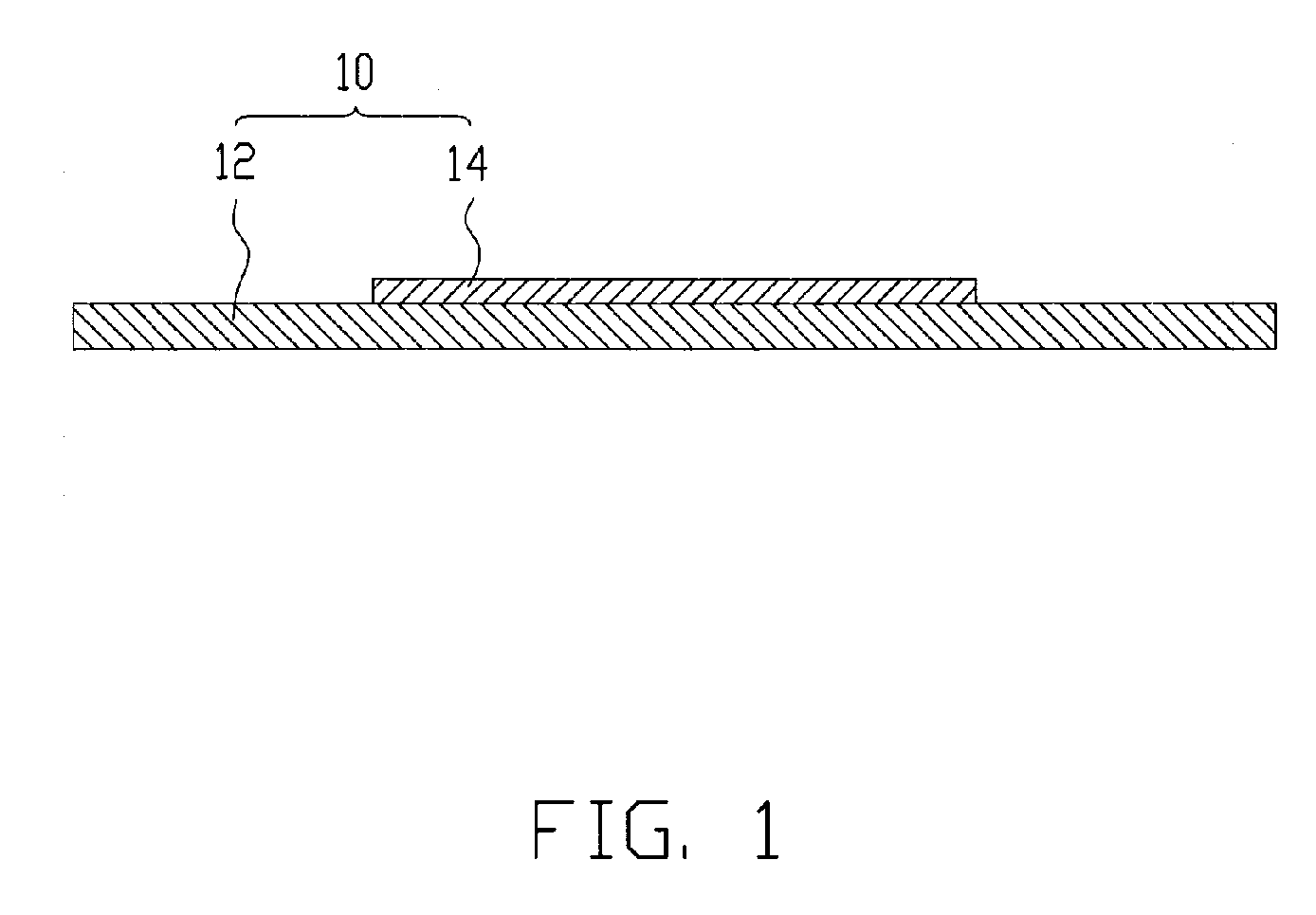
[0012]FIG. 1 is a cross-sectional view of a diaphragm 10 in accordance with the present invention. The diaphragm 10 is used for micro-electroacoustic transducers, such as the loudspeakers of mobile phones or notebooks. In the preferred embodiment, the diaphragm 10 is tubular-shaped and round as viewed from above. The diaphragm 10 comprises a first layer 12 and a second layer 14. The first layer 12 comprises a covered region located at a central portion thereof and an exposed region surrounding the covered region. The diameter of the second layer 14 is smaller than that of the first layer 12. The second layer 14 overlaps on the covered region of the first layer 12 and is substantially concentric with the first layer 12. Thus, the thickness of the central portion of the diaphragm 10 is larger than that of the peripheral portion of the diaphragm 10. The first and second layers 12, 14 are made of a polymeric material, such as PEI, PI, PP, PEN or PET.

[0013] Generally, the thickness of a ...

second embodiment

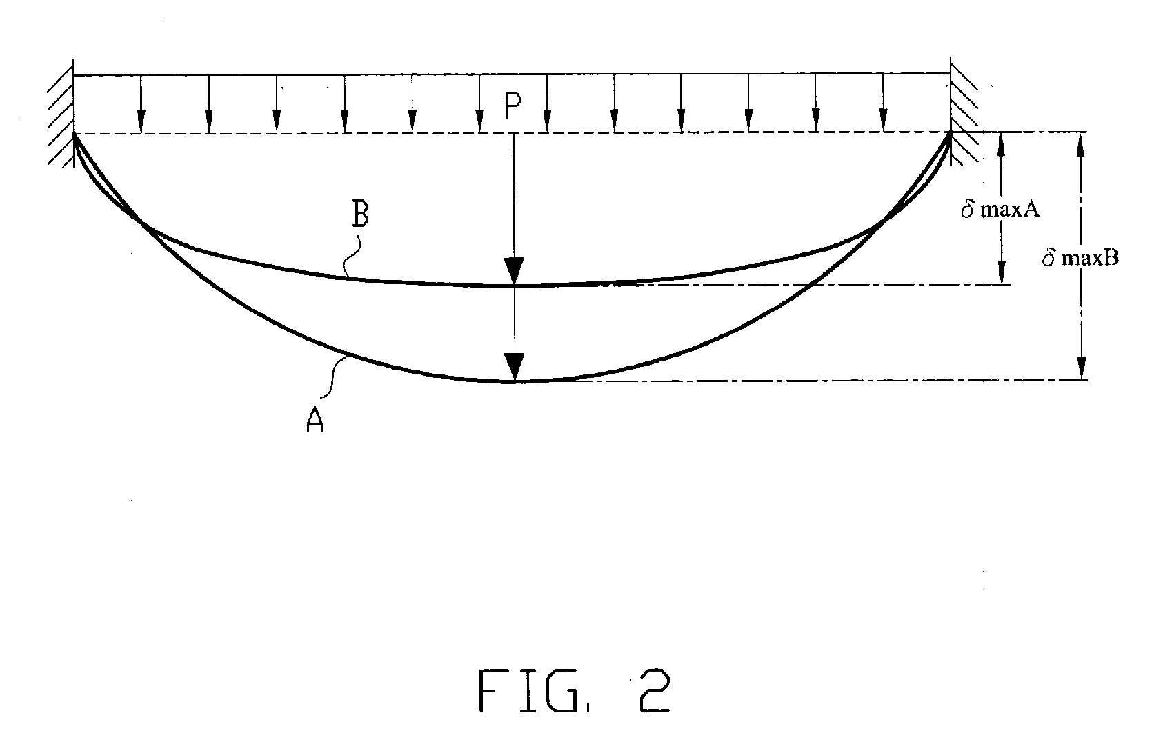
[0017] Table 2 shows that as the density ratio of the second layer 14 to the first layer 12 is increased the rigidity of the diaphragm 10 increases also, which results in the maximum deformation displacement of the diaphragm 10 being reduced when the density of the second layer 14 is increased. [0016]FIG. 3 shows a cross-sectional view of a diaphragm 20 in accordance with the present invention. The diaphragm 20 is integrally formed and has a circular bump 24 formed at a central portion thereof. The thickness of the central portion of the diaphragm 20 is therefore larger than that of the peripheral portion of the diaphragm 20, which results in the rigidity of the diaphragm 20 being increased. The periphery of the bump 24 is preferable concentric with the periphery of the diaphragm 20.

third embodiment

[0018]FIG. 4 shows a cross-sectional view of a diaphragm 30 in accordance with the present invention. The diaphragm 30 comprises a first layer 32 and a second layer 34. The first layer 32 defines a recess in a central portion of a top surface thereof. The second layer 34 is received in the recess of the first layer 32. The depth of the recess of the first layer 32 is the same as the thickness of the second layer 34 so that the top surface of the first layer 32 is coplanar with the top surface of the second layer 34. The second layer 34 is made of a material which has a larger density than that of the first layer 32. Thus, the rigidity of the central portion of the diaphragm 30 is increased which results in the rigidity of the diaphragm 30 being increased. Alternatively, the depth of the recess of the first layer 32 may be smaller than the thickness of the second layer 34 to allow the second layer 34 to protrude from the first layer 32.

[0019] In the present invention, the diaphragms ...


PUM


Abstract

A diaphragm for a micro-electroacoustic transducer, includes a first layer including an exposed region and a covered region, and a second layer. The second layer overlaps the covered region of the first layer to thereby increase the rigidity of the diaphragm. The covered region is surrounded by the exposed region.

Description

FIELD OF THE INVENTION [0001] The present invention relates generally to a micro-electroacoustic device, and more particularly to a diaphragm of a micro-electroacoustic device. DESCRIPTION OF RELATED ART [0002] Sound is one important means by which people communicate with each other, thus creating new methods for sound transference allows greater communication between people. Electroacoustic transducers are key components in transferring sound. A typical electroacoustic transducer has a magnetic circuit in which a magnetic field generated by a magnet passes through a base member, a magnetic core and a diaphragm and returns to the magnet again. When an oscillating electric current is supplied to a coil wound around the magnetic core, the corresponding oscillating magnetic field generated by the coil is then superimposed onto the magnetostatic field of the magnetic circuit. The resulting oscillation generated in the diaphragm is then transmitted to the air as sound. The basic loudspea...

Claims


Application Information

Patent Timeline
Patent Type & Authority Applications(United States)
IPC IPC(8): G10K13/00H04R7/00
CPCH04R7/06H04R2499/11H04R2307/029
Inventor YANG, TSUNG-LUNG
Owner HON HAI PRECISION IND CO LTD
Why Eureka
Try Eureka