Vehicle headlight control using imaging sensor

a technology of imaging sensor and headlight control, which is applied in the direction of vehicle cleaning, optical radiation measurement, instruments, etc., can solve the problems of ineffective approaches, inability to reliably detect the taillights of leading vehicles, and ineffective prior art vehicle headlight dimming controls

Inactive Publication Date: 2007-02-01
MAGNA ELECTRONICS
View PDF98 Cites 156 Cited by
  • Summary
  • Abstract
  • Description
  • Claims
  • Application Information

AI Technical Summary

Benefits of technology

[0005] The present invention provides a vehicle control which is capable of identifying unique characteristics of light sources based upon a precise evaluation of light source characteristics made in each portion of the scene forward of the vehicle, in the vicinity of each light source, by separating each light source from the remainder of the scene and analyzing that source to determine its characteristics. One characteristic used in identifying a light source is the spectral characteristics of that s...

Problems solved by technology

Such approaches have been ineffective.
Such prior art vehicle headlight dimming controls have also been ineffective at reliably detecting the taillights of leading vehicles.
The apparent reason is that the characteristics of these two light so...

Method used


Image

  • Vehicle headlight control using imaging sensor
  • Vehicle headlight control using imaging sensor
  • Vehicle headlight control using imaging sensor

Examples


Embodiment Construction

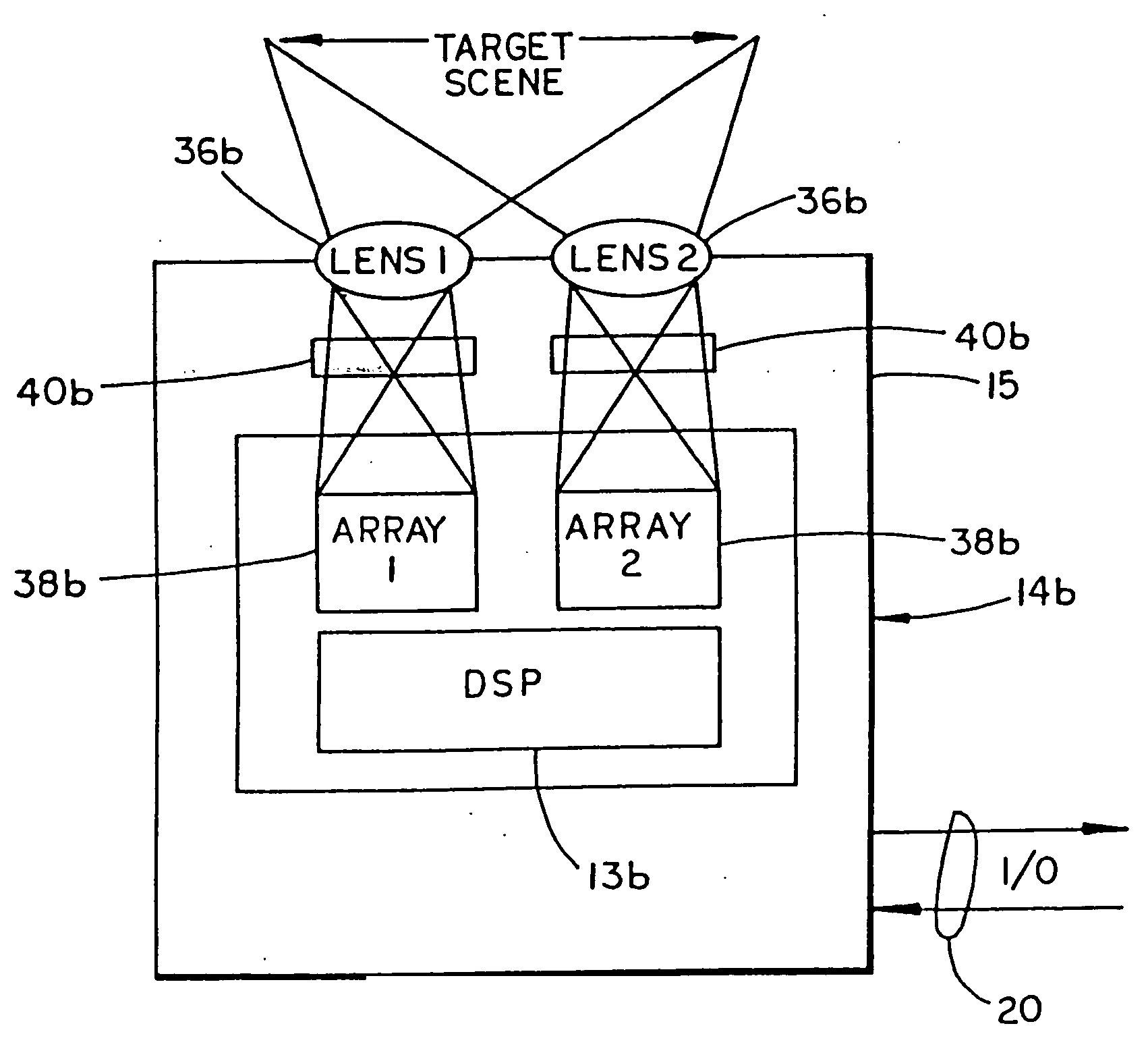
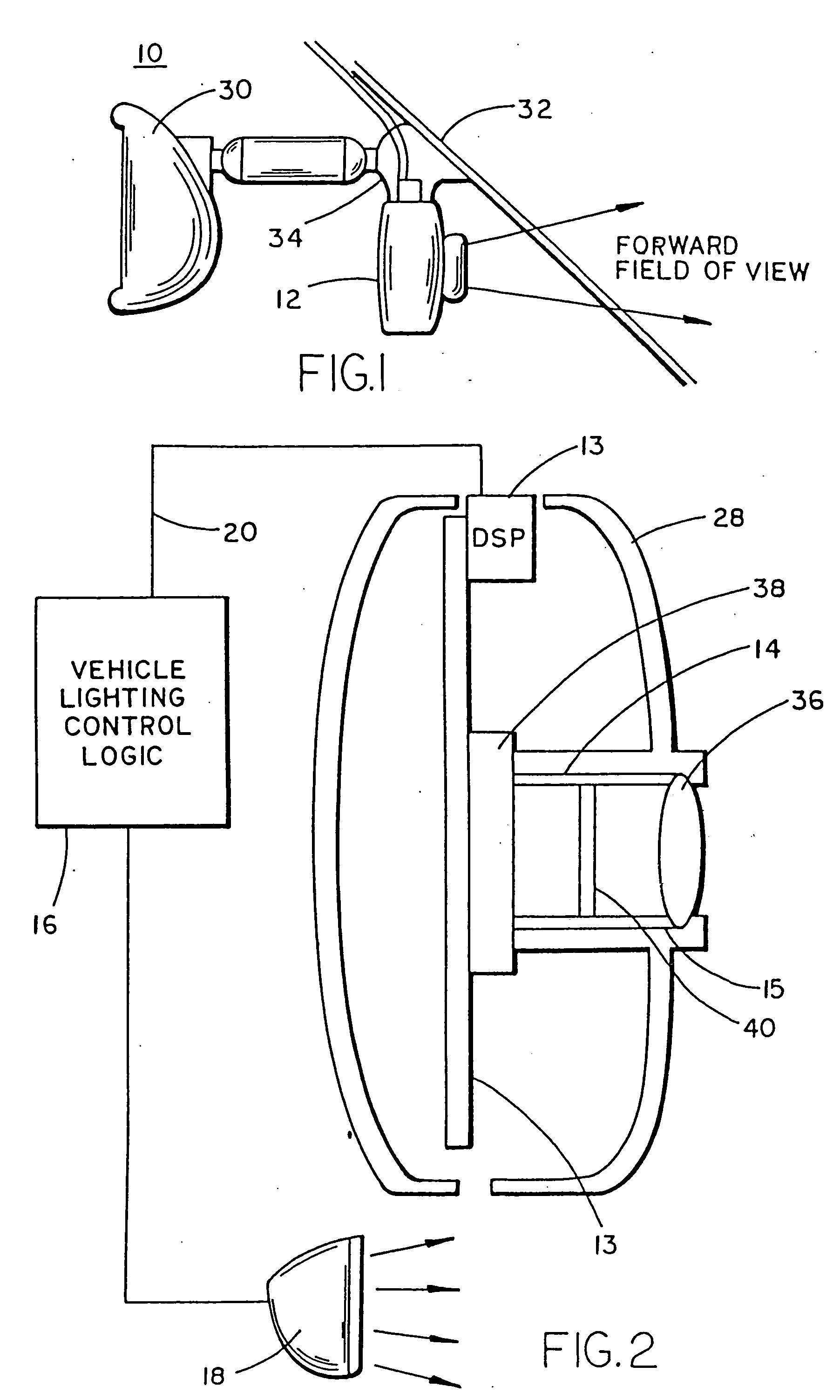
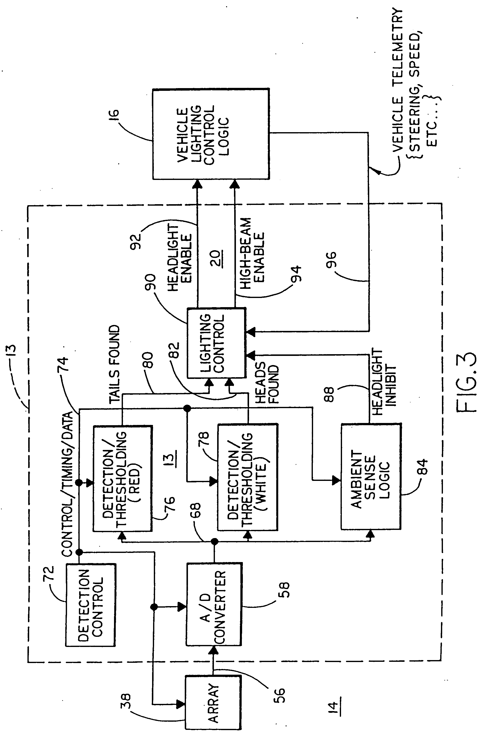
[0024] Referring now specifically to the drawings and the illustrative embodiments depicted therein, a vehicle 10 includes a vehicle headlight dimming control 12 made up of an imaging sensor module 14 which senses light from a scene forward of vehicle 10, an imaging control circuit 13 which receives data from sensor 14, and a vehicle lighting control logic module 16 which exchanges data with control circuit 13 and controls headlamps 18 for the purpose of modifying the headlight beam (FIGS. 1 and 2). Such control may be a binary control of the aim of the beam, such as by switching between lamps or lamp filaments, or may be a continuous variation of the aim of a single lamp more or less forward of the vehicle. The control may also control the intensity or pattern of the beam. Additionally, the lights of a vehicle equipped with daytime running lights may be switched between a daytime running light condition and a low-beam condition. Vehicle headlight dimming control 12 can perform a wi...


PUM


Abstract

A vehicle headlamp control method and apparatus includes providing an imaging sensor that senses light in spatially separated regions of a field of view forward of the vehicle. Light levels sensed in individual regions of the field of view are evaluated in order to identify light sources of interest, such as oncoming headlights and leading taillights. The vehicle's headlights are controlled in response to identifying such particular light sources or absence of such light sources. Spectral signatures of light sources may be examined in order to determine if the spectral signature matches that of particular light sources such as the spectral signatures of headlights or taillights. Sensed light levels may also be evaluated for their spatial distribution in order to identify light sources of interest.

Description

CROSS-REFERENCE TO RELATED APPLICATIONS [0001] This application is a continuation of U.S. patent application, Ser. No. 09 / 441,341, filed Nov. 16, 1999 (Attorney Docket DON01 P-770), which is a continuation of U.S. patent application Ser. No. 09 / 135,565, filed Aug. 17, 1998, now U.S. Pat. No. 6,097,023, which is a continuation of U.S. patent application Ser. No. 08 / 621,863, filed Mar. 25, 1996, now U.S. Pat. No. 5,796,094, which is continuation-in-part of U.S. patent application Ser. No. 08 / 023,918 filed Feb. 26, 1993, by Kenneth Schofield and Mark Larson, now U.S. Pat. No. 5,550,677, and the present application is a continuation-in-part U.S. patent application, Ser. No. 11 / 246,593, filed Oct. 6, 2005 by Schofield et al. for VEHICULAR VISION SYSTEM (Attorney Docket DON01 P-1244), which is a continuation of U.S. patent application Ser. No. 10 / 940,700, filed Sep. 14, 2004, now U.S. Pat. No. 6,953,253, which is a continuation of U.S. patent application Ser. No. 10 / 372,873, filed Feb. 24...

Claims


Application Information

Patent Timeline
IPC IPC(8): H01L27/00
CPCB60Q1/1423G01J3/513B60Q2300/056B60Q2300/21B60Q2300/312B60Q2300/314B60Q2300/41B60Q2300/42B60R2001/1223B60S1/0822B60S1/0844B60S1/087G01J1/0488G01J1/4228G01J3/02G01J3/36G01J3/51B60Q2300/054G06V20/56
Inventor SCHOFIELD, KENNETHLARSON, MARK L.VADAS, KEITH J.
Owner MAGNA ELECTRONICS
Why Eureka
Try Eureka