Vehicle equipment control system and method

Inactive Publication Date: 2007-02-01
DENSO CORP
View PDF14 Cites 16 Cited by
  • Summary
  • Abstract
  • Description
  • Claims
  • Application Information

AI Technical Summary

Benefits of technology

[0013] In a vehicle equipment control system according to one aspect of the present invention, in the event that a trigger switch for directing locking of a vehicle door is not operated, a communication area for the communication between an inside transmitter and a portable unit is set to be large in comparison to the case where the trigger switch is operated. Accordingly, when locking the respective vehicle doors according to the auto-lock system, the system makes it possible to set the communication area covering the entire c

Problems solved by technology

However, in the case that the vehicle door lockable by using any one of the auto-lock and trigger lock systems, such drawbacks as described below may arise.
However, this approach encounters difficulty in setting a transmission range of the request signal of the inside transmitter to include the overall area in the compartment into a communication area that enables communication with the portable unit.
Consequently, while the user is carrying the portable unit, an alarm indicating that the portable unit has been forgotten in

Method used


Image

  • Vehicle equipment control system and method
  • Vehicle equipment control system and method
  • Vehicle equipment control system and method

Examples


Embodiment Construction

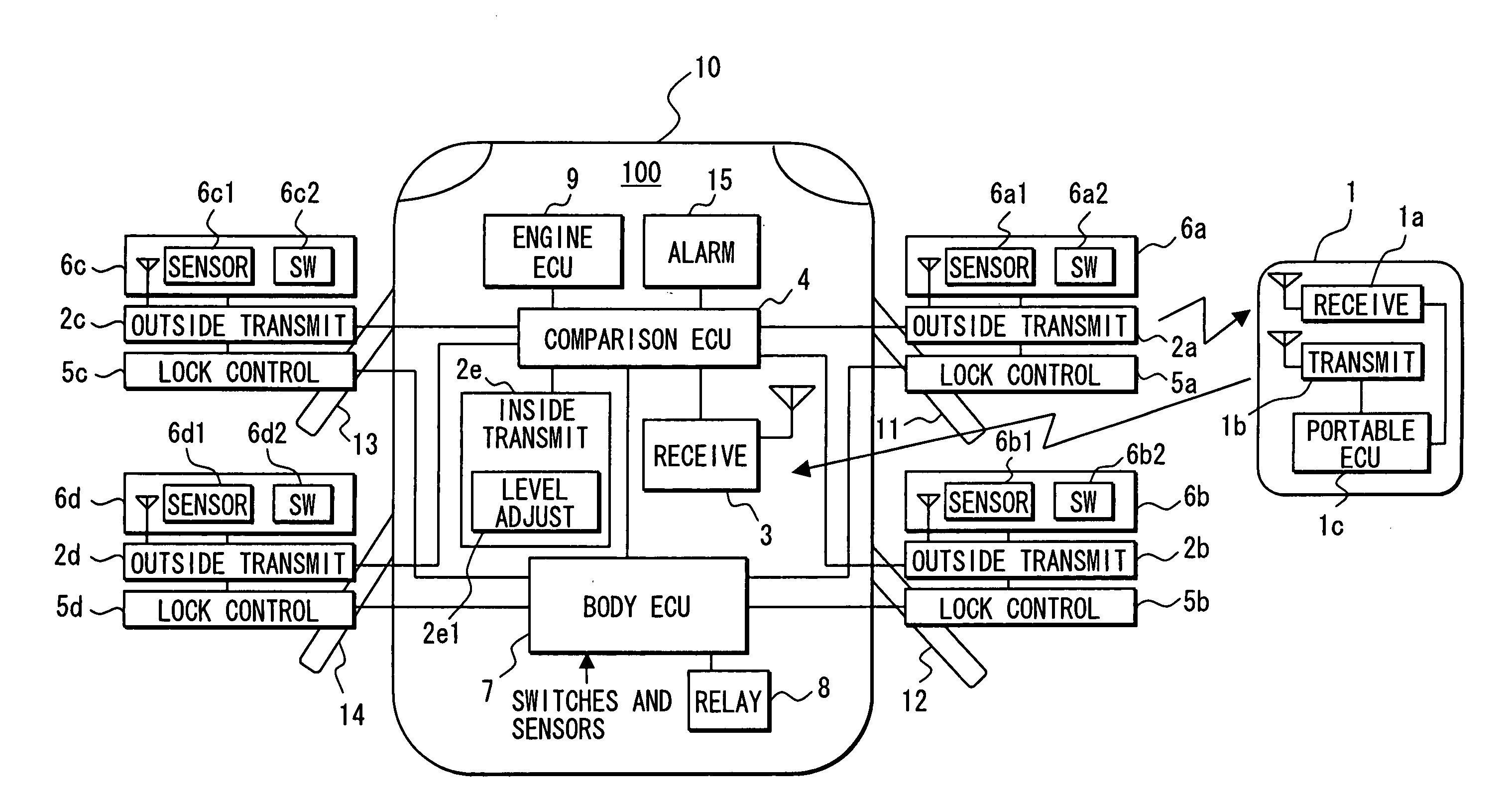
[0022] A vehicle equipment control system according to an embodiment is shown in FIG. 1. The system controls a lock or unlock mode of each door of a vehicle 10 in accordance with comparison of identification (ID) codes through two-way communication between a portable unit 1 and an in-vehicle unit 100 provided in the vehicle 10. The in-vehicle unit 100 controls a permission or inhibition mode for starting an engine of the vehicle 10 to improve security of the vehicle 10.

[0023] The portable unit 1 includes a receiver 1a and a transmitter 1b. The receiver 1a receives a request signal from either one of outside transmitters 2a to 2d or an inside transmitter 2e of the in-vehicle unit 100. In response to the received request signal, the transmitter 1b transmits a request signal including, for example, an ID code. A portable unit ECU 1c is connected to the receiver 1a and the transmitter 1b, and executes various control processes and operations. More specifically, the portable unit ECU 1c...


PUM


Abstract

A vehicle equipment control system locks vehicle doors by any one of auto-lock and trigger lock systems. In the auto-lock system, a wide communication area is set that covers an entire vehicle compartment is set. In the trigger lock system, a narrow communication area is set that disables the communication with a portable unit carried by a user near a vehicle. When no response signal is received from the portable unit in the respective communication areas, the respective vehicle doors are locked. Accordingly, even when any one of the auto-lock and trigger lock systems is used, the portable unit is prevented from being left in the compartment, and the respective vehicle doors can be locked.

Description

CROSS REFERENCE TO RELATED APPLICATION [0001] This application is based on and incorporates herein by reference Japanese Patent Application No. 2005-223296 filed on Aug. 1, 2005. FIELD OF THE INVENTION [0002] The present invention relates to vehicle equipment control system and method that allow two-way communication between a portable unit and an in-vehicle unit and that controls vehicle equipment mounted in a vehicle in accordance with the result of the communication. BACKGROUND OF THE INVENTION [0003] Conventionally, JP-2003-269023A for example, proposes a vehicle equipment control system. The system has an auto-lock function for automatically locking vehicle doors when a user leaves a vehicle. In the system, the distance permitting auto-locking is specifiable. When a “short distance” is specified, then the auto-lock function is executed upon the condition where LF (low frequency) communication from the vehicle device to the portable unit becomes disabled. On the other hand, when...

Claims


Application Information

Patent Timeline
IPC IPC(8): B60R25/00B60R25/01B60R25/04B60R25/10B60R25/24B60R25/30B60R25/34E05B49/00
CPCB60R25/245G07C2209/63G07C2009/00793G07C9/00309
Inventor TESHIMA, KENTARONAKASHIMA, KAZUHIRO
Owner DENSO CORP
Why Eureka
Try Eureka