Unlock instant, AI-driven research and patent intelligence for your innovation.

Apparatus and method for continuous conduction mode boost voltage power factor correction with an average current control mode

a technology of boost voltage and power factor, which is applied in the direction of electric variable regulation, process and machine control, instruments, etc., can solve the problems of high thd, complex design, and inability to achieve high power factor and low total harmonic distortion

Inactive Publication Date: 2007-02-01
NIKO SEMICON +1
View PDF7 Cites 14 Cited by
  • Summary
  • Abstract
  • Description
  • Claims
  • Application Information

AI Technical Summary

Benefits of technology

[0011] The main object of the present invention is to provide a simpler and superior CCM boost voltage power factor correction apparatus with a current-averaging control mode. The apparatus is used for an AC / DC electrical power converter. The apparatus uses a duty signal outputted from an oscillator to control a switch to trim the input current of the AC / DC electrical power converter and make the input current have a sine waveform with a phase that is the same as the input voltage. The present invention utilizes resettable integrators to obtain integration operation for the output voltage signal of a voltage error amplifier and the sensed input current signal. The integrated signal is then compared to control the duty cycle of the switch. This method makes the input port of the AC / DC electrical power converter resistive hence achieving high power factor. Thereby, the input current and the input voltage have a proportion relation and the phase is the same as each other.
[0016] The CCM boost voltage power factor correction apparatus with a current-averaging control mode of the present invention is used for an AC / DC electrical power converter. The apparatus uses integrators to integrate the difference voltage signal obtained from comparison and the input current signal obtained from detection. Next, the integration result is compared to control the duty cycle of the switch. Thereby, the input current and the input voltage in the AC / DC electrical power converter have a proportion relation and their phases are the same as each other. The components used in this control method are simpler than the PFC circuit of the prior art. It is easy to integrate in one chip with fewer pins. The apparatus of the present invention has a high power factor and a low total harmonic distortion (THD).

Problems solved by technology

However, building a lot of electrical power plants is not the only way to achieve the goal.
The major drawback of DCM PFC is its high THD due to large ripple current.
The power factor correction having a multiplier needs a lot of components and its design is complex.
It is difficult to design a single chip because of the large number of components and pin numbers needed for the chip.

Method used


Image

  • Apparatus and method for continuous conduction mode boost voltage power factor correction with an average current control mode
  • Apparatus and method for continuous conduction mode boost voltage power factor correction with an average current control mode
  • Apparatus and method for continuous conduction mode boost voltage power factor correction with an average current control mode

Examples


first embodiment

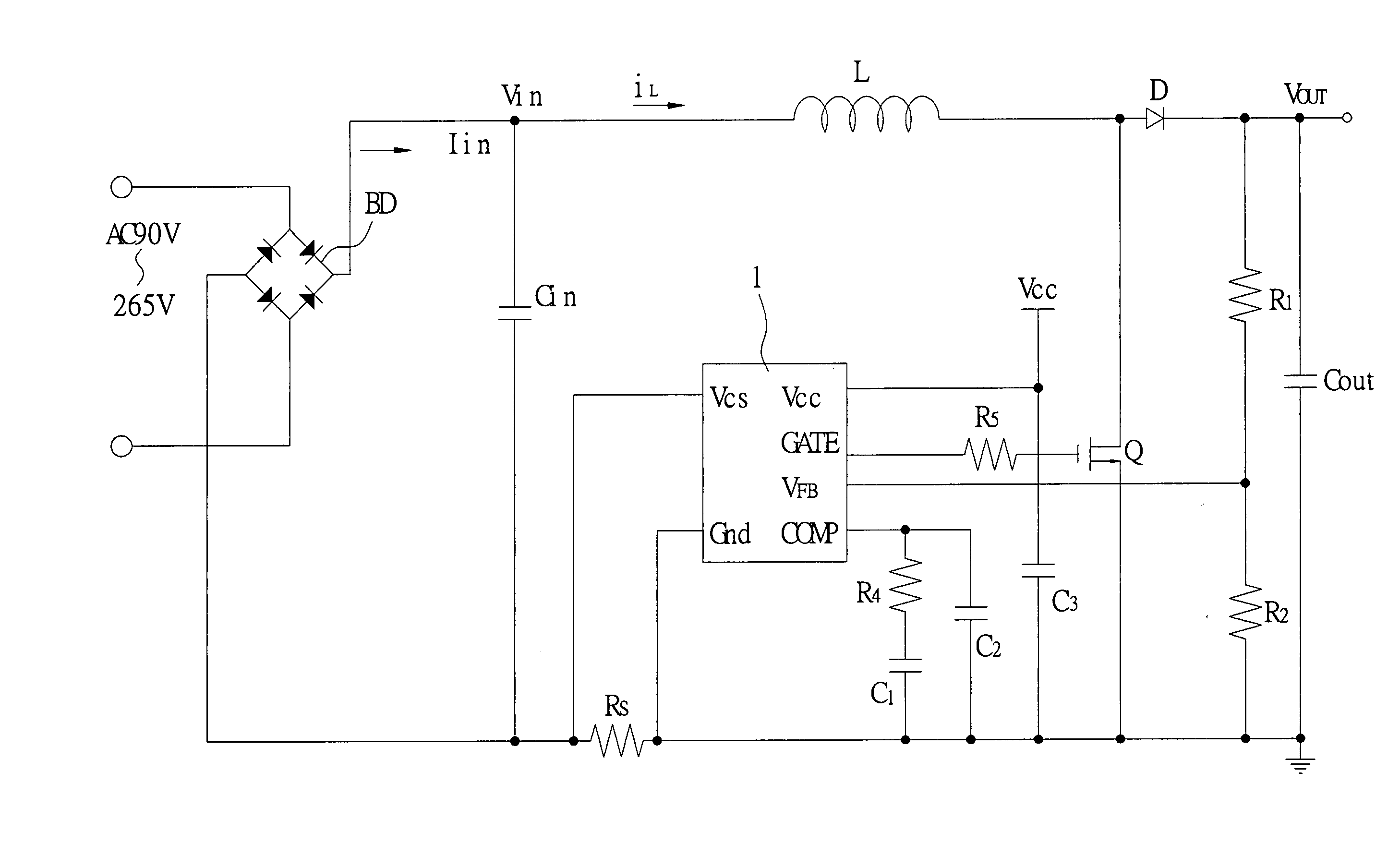
[0033]FIG. 5 shows a structure diagram of the present invention used in an AC / DC electrical power converter of the The CCM boost voltage power factor correction apparatus 1 with a current-averaging control mode of the present invention controls the duty switch operation of a switch Q and makes the input current Iin follow the input voltage Vin rectified by a rectification element BD. Therefore, the input current Iin and the input voltage Vin in the AC / DC electrical power converter have a proportion relation and their phases are the same as each other. The apparatus of the present invention has a high power factor and a low total harmonic distortion (THD).

[0034]FIG. 6 shows a circuit block diagram of the first embodiment of the present invention. Please refer to FIGS. 5 and 6. The CCM boost voltage power factor correction apparatus 1 with a current-averaging control mode of the present invention is used for an AC / DC electrical power converter. The CCM boost voltage power factor corr...

second embodiment

[0042] Please refer to FIGS. 5 and 8. FIG. 8 shows a circuit block diagram of the present invention. The continuous boost voltage power factor correction apparatus 1 with the current-averaging control mode of the present invention is used for an AC / DC electrical power converter. The continuous boost voltage power factor correction apparatus 1 with a current-averaging control mode uses a cycle signal clock outputted from a oscillator 15 to control a switch Q to trim the input current Iin of the AC / DC electrical power converter and make the input current Iin have a sine waveform and a phase that is the same as the input voltage Vin.

[0043] The second embodiment of the CCM boost voltage power factor correction apparatus 1 with a current-averaging control mode of the present invention further comprises an adder 13. The adder 13 connects with the first resettable integrator 12 and the second resettable integrator 16 for adding the first output signal VX and the second output signal VY to ...

third embodiment

[0052] Please refer to FIGS. 10 and 11. FIG. 11 shows a circuit block diagram of the present invention. The CCM boost voltage power factor correction apparatus 2 with a current-averaging control mode of the present invention is used for an AC / DC electrical power converter. The CCM boost voltage power factor correction apparatus 2 with a current-averaging control mode uses a cycle signal clock outputted from a oscillator 25 to control a switch Q to trim the input current Iin of the AC / DC electrical power converter and make the input current Iin have a sine waveform and its phase be the same as the input voltage Vin. The power factor correction apparatus 2 uses a voltage error amplifier 20 connected with the output port of the AC / DC electrical power converter to obtain a voltage feedback signal VFB via a dividing resistor R2. The voltage error amplifier 20 compares the voltage feedback signal VFB with a reference voltage Vref to output a difference voltage signal VM1.

[0053] A resettab...


PUM


Abstract

The continuous conduction mode (CCM) boost voltage power factor correction apparatus with an average-current control mode of the present invention uses resettable integrators to integrate the difference voltage signal outputted from the voltage error amplifier and the input current signal obtained from detection. The integration results are then compared to control the duty cycle of the switch. Thereby, the input current and the input voltage in the AC / DC electrical power converter have a proportion relation and their phases are the same as each other. The components used in this control method are simpler than the PFC circuit of the prior art. It is easy to integrate in one chip with fewer pins. The apparatus of the present invention has a high power factor and a low total harmonic distortion (THD).

Description

BACKGROUND OF THE INVENTION [0001] 1. Field of the Invention [0002] The present invention relates to a continuous conduction mode (CCM) boost voltage power factor correction apparatus with an average current control mode. In particular, a power factor correction apparatus and a method utilizing a resettable integrator to achieve high power factor and low total harmonic distortion (THD) for an electrical power system. [0003] 2. Description of the Related Art [0004] A high quality electrical power supply is a desired goal for every country in the world. However, building a lot of electrical power plants is not the only way to achieve the goal. For achieving the goal effectively, on the one hand a country can increase their electrical power supply, on the other hand they can also improve the power factor or the efficiency of electrical appliances. [0005] A power factor correction (PFC) is used for making the input voltage of an electrical appliance in phase with the input current. Ther...

Claims


Application Information

Patent Timeline
IPC IPC(8): G05F1/00
CPCG05F1/70
Inventor WU, CHUNG-CHENGHUANG, QINZHU, NINGZHANG, XIN
Owner NIKO SEMICON