

Sealing device
- Summary
- Abstract
- Description
- Claims
- Application Information
AI Technical Summary
Benefits of technology
Problems solved by technology
Method used
Image

Examples
first embodiment
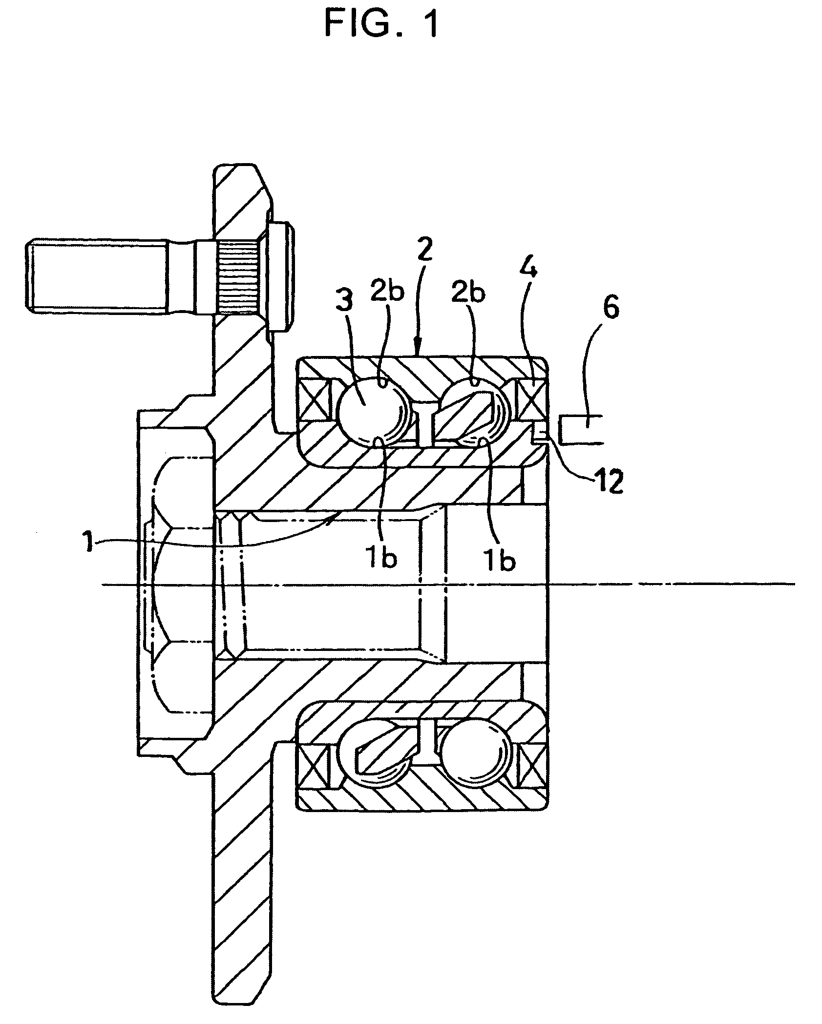
[0039] As shown in FIG. 1, the sealing devices are attached to both ends so as to seal an annular space formed by an inner member 1 and an outer member 2 which rotate relatively to each other via a rolling element 3. A sealing device 4 in one end is provided with a magnetic encoder 12 measuring a rotating speed. The inner member 1 and the outer member 2 have raceway surfaces of the rolling element 3, and each of the raceway surfaces is formed in a groove shape. The inner member 1 and the outer member 2 may be single elements of a bearing inner ring and a bearing outer ring, or assembled members of the bearing inner ring and the bearing outer ring with the other parts respectively. Further, the inner member 1 may be a shaft. The sealing device can be used, for example, in a rotating part of a motor vehicle, an electrical appliance, an industrial machinery, a bicycle or the like.
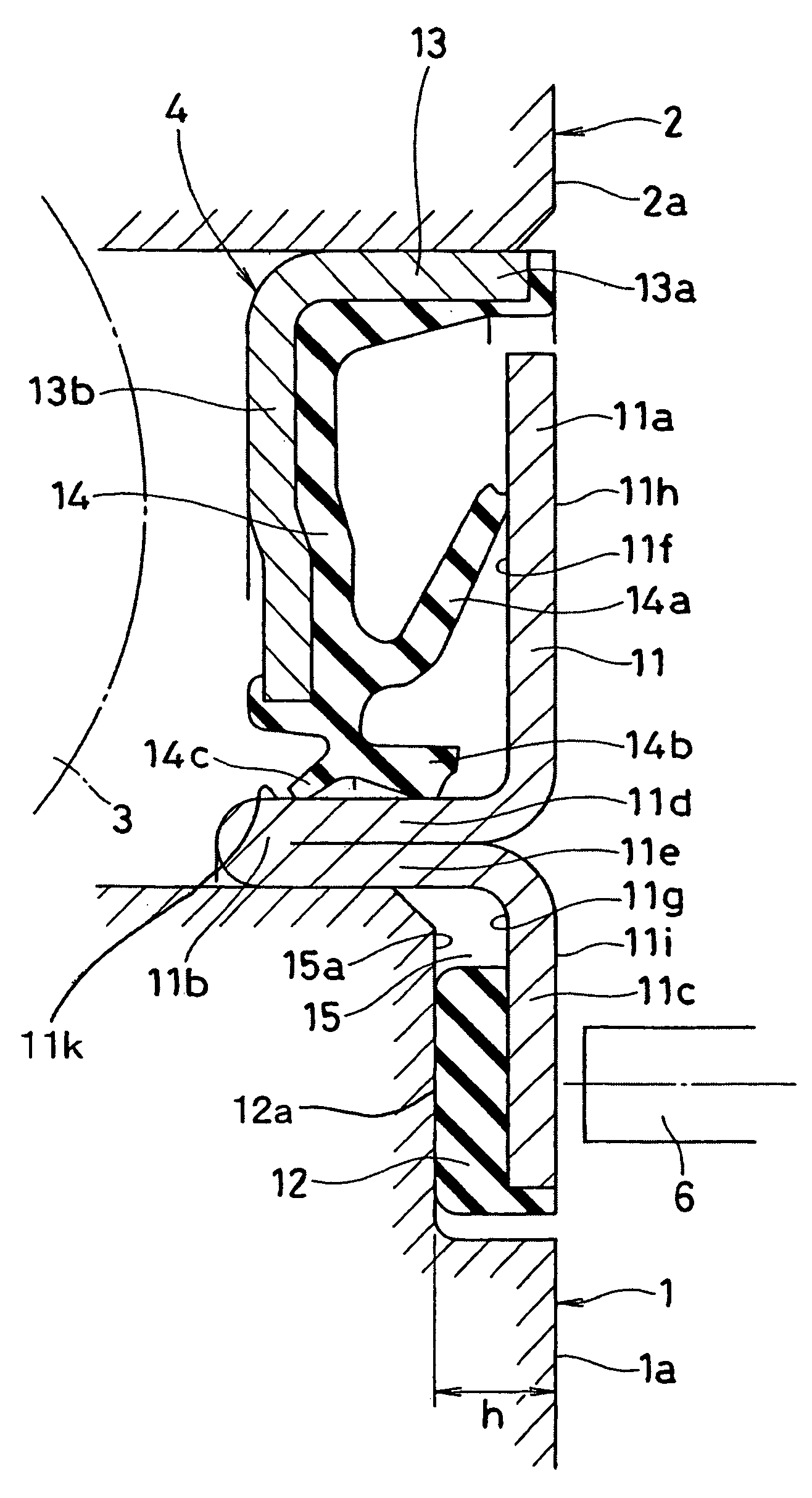
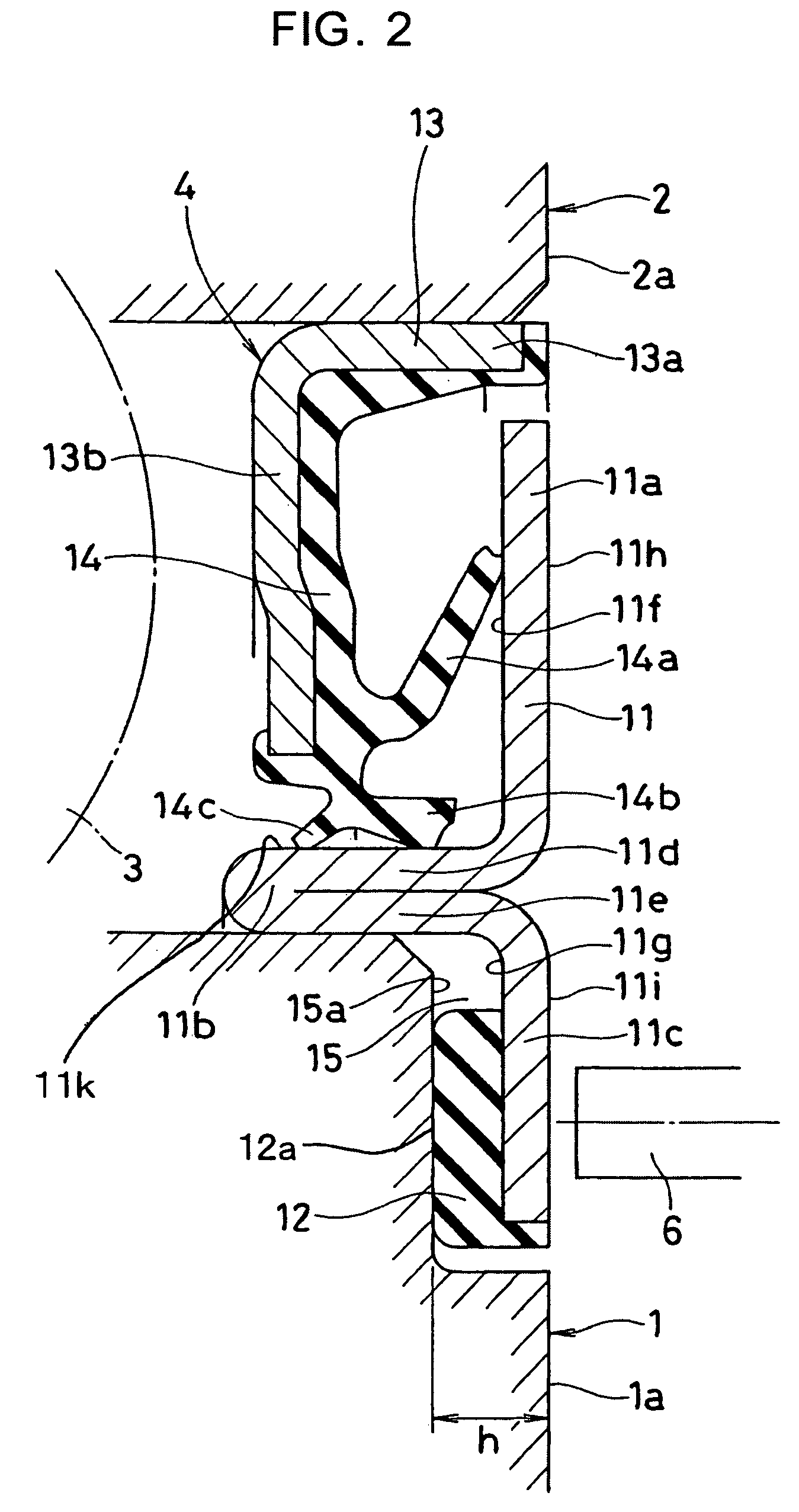
[0040] As shown in FIG. 2, the sealing device 4 seals an annular gap between the housing 2 serving as the ...
second embodiment
[0048]FIG. 4 is a cross sectional view of a sealing device in accordance with a second embodiment of the present invention. As shown in FIG. 4, a sealing device 4 in accordance with the second embodiment is structured by changing a depth h of the recess portion 15 formed in the axial end portion of the shaft 1 in accordance with the first embodiment, and is structured such that an axial position of the outer surface 11i of the protecting diametrical direction portion 11c is arranged at the inner side from the outer surface 11h of the sealing diametrical direction portion 11a, and the axial end surface 1a of the shaft 1 and the axial end surface 2a of the housing 2, and the magnetic sensor 6 is arranged within the recess portion 15.
[0049] In this case, in the first embodiment and the second embodiment, the material forming the magnetic encoder 12 may be a synthetic resin such as a plastic or the like in addition to the rubber material.
[0050] Further, a shape, a direction, a number ...
third embodiment
[0052]FIG. 5 is a cross sectional view of a sealing device 4 in accordance with a third embodiment of the present invention.
[0053] The sealing device 4 in accordance with the present embodiment is a sealing device provided with a magnetic encoder capable of detecting a rotation of two relatively rotating members, and can be employed, for example, in a rotating part of a motor vehicle, an electrical appliance, an industrial machinery, a bicycle or the like. Further, in the case of being applied to the motor vehicle, the sealing device 4 can be preferably used in a hub bearing unit with an ABS vehicle speed sensor, for example, as a hub seal with a magnetic encoder for sealing a gap between a hub bearing unit (housing) and a drive shaft.
[0054] As shown in FIG. 5, the sealing device 4 is structured such as to seal an annular gap between a housing 2 serving as the other member in two members provided so as to be rotatable relatively to each other coaxially, and a shaft 1 serving as on...
PUM
 Abstract
Description
Claims
Application Information