
Liquid crystal display device, display control method and display control apparatus

a display device and liquid crystal technology, applied in the direction of instruments, static indicating devices, etc., can solve the problems of increasing manufacturing costs, lowering efficiency, and difficulty in applying the dynamic bend system to a large-sized liquid crystal display panel of a large size. , to achieve the effect of preventing the occurrence of reverse transition

Inactive Publication Date: 2007-02-01
TOSHIBA MATSUSHITA DISPLAY TECH
View PDF14 Cites 12 Cited by
  • Summary
  • Abstract
  • Description
  • Claims
  • Application Information

AI Technical Summary

Benefits of technology

[0013] An object of this invention is to provide a liquid crystal display device, display control method and display control apparatus which can prevent occurrence of reverse transition of liquid crystal molecules caused by a variation in the application environment.
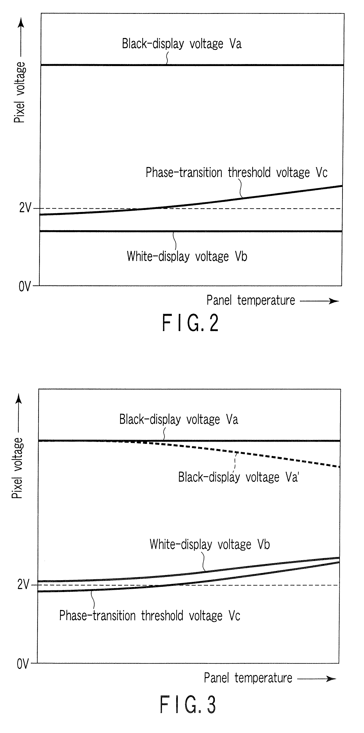
[0017] In the liquid crystal display panel, the display control method and the display control apparatus, the minimum value of the liquid crystal drive voltage or the pixel voltage is determined based on the phase-transition threshold voltage which causes energy of the splay alignment and energy of the bend alignment to be balanced with each other in an application environment (temperature, drive frequency, or the like) of the liquid crystal display panel. That is, even when the panel temperature, the drive frequency or the like varies, the liquid crystal drive voltage can be maintained in a range in which the alignment state of liquid crystal molecules is not reverse-transitioned from the bend alignment to the splay alignment. Thus, occurrence of reverse transition of the liquid crystal molecules caused by a variation in the application environment can be prevented.

Problems solved by technology

However, reverse transition from the bend alignment to the splay alignment tends to occur if a voltage-non-applied state, or a voltage-applied state of a voltage not greater than a level at which energy of the splay alignment is balanced with energy of the bend alignment, continues for a long time.
Thus, it is difficult to apply the dynamic bend system to a large-sized liquid crystal display panel of a large size.
When the black insertion driving is required for a liquid crystal display panel with a diagonal of, for example, 32 inches, existing driver ICs are not usable in the black insertion driving.
If the backlight unit is made of an LED light source, it becomes possible to turn on and off the backlight unit at such a high frequency, but it is necessary to accept an increase in the manufacturing cost and a lowering in the efficiency.
On the other hand, if the backlight unit is made of a cold-cathode fluorescent tube operable at a frequency lower than approximately 900 Hz, it is difficult to turn on and off the cold-cathode fluorescent tube at a high frequency exceeding the above frequency.
However, in the conventional liquid crystal display panel utilizing the static bend system, reverse transition may occur in some cases due to a variation in the application environment such as panel temperature and drive frequency.

Method used


Image

  • Liquid crystal display device, display control method and display control apparatus
  • Liquid crystal display device, display control method and display control apparatus
  • Liquid crystal display device, display control method and display control apparatus

Examples


first embodiment

[0038] There will now be described a liquid crystal display device according to this invention with reference to the accompanying drawings.

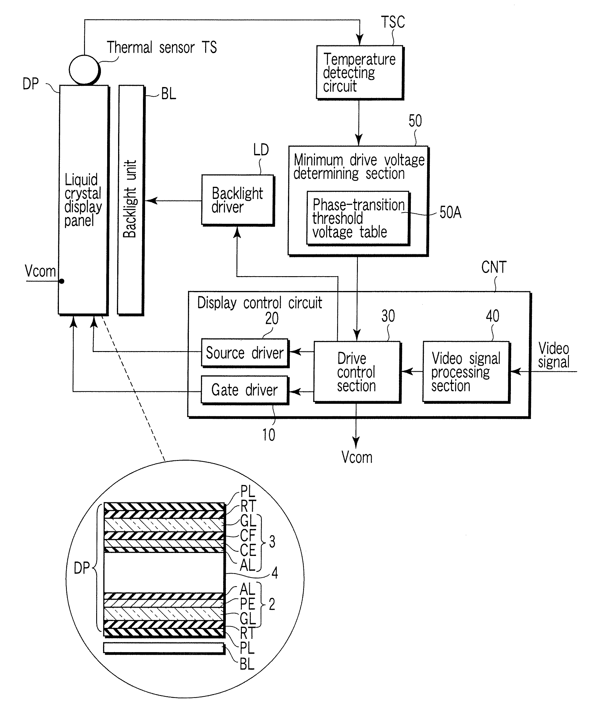
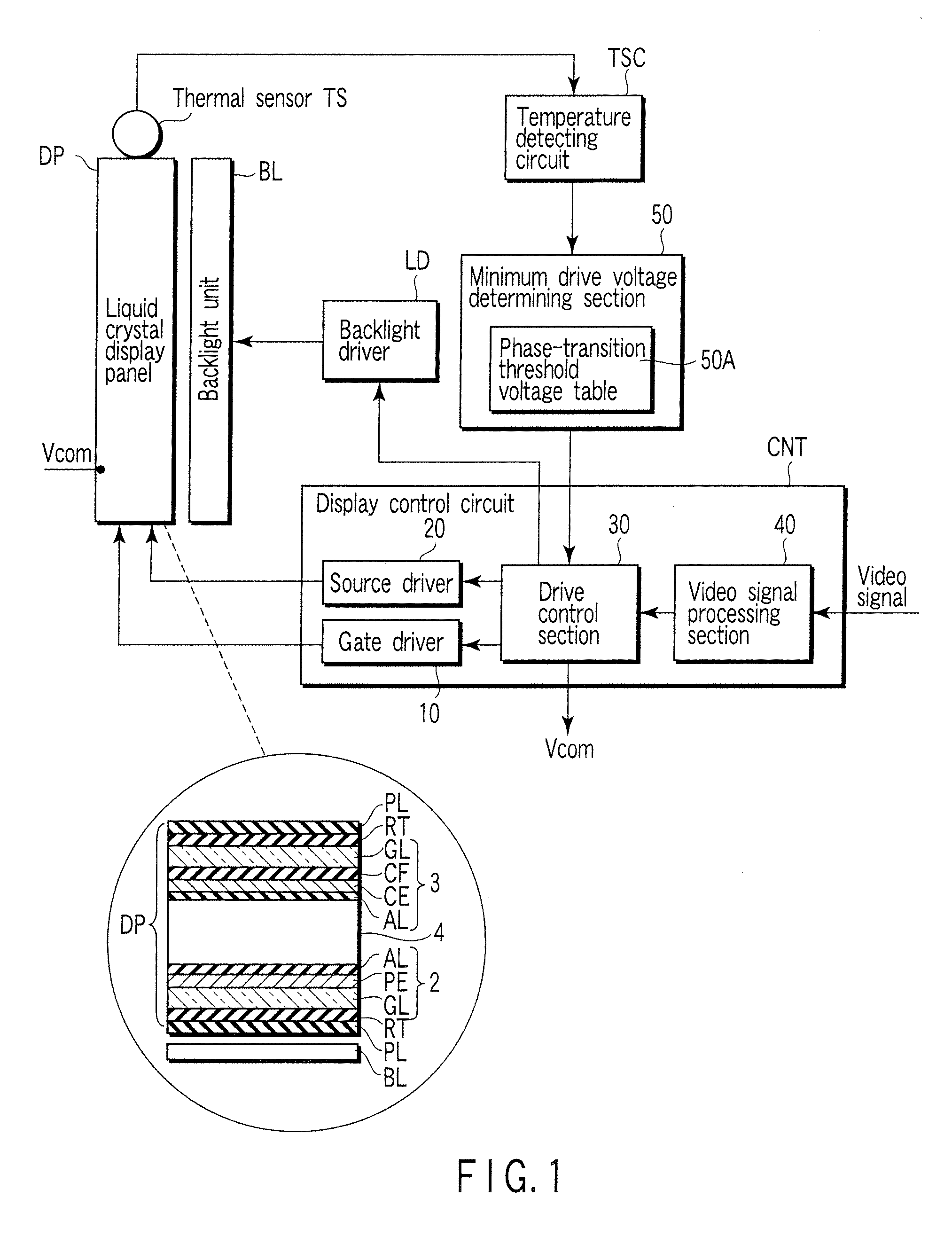
[0039]FIG. 1 schematically shows the circuit configuration of a liquid crystal display device. The liquid crystal display device includes an OCB-mode liquid crystal display panel DP of a transmissive type, backlight unit BL, thermal sensor TS, temperature detecting section TSC, minimum drive voltage determining section 50, display control circuit CNT and backlight driver LD.

[0040] The liquid crystal display panel DP includes an array substrate 2, a counter substrate 3, and a liquid crystal layer 4 held between the array substrate 2 and the counter substrate 4. The array substrate 1 includes a grass plate GL serving as a transparent insulating substrate, a plurality of pixel electrodes PE made of ITO and serving as transparent electrodes arranged on the glass plate GL, and an alignment film AL covering the pixel electrodes PE. The counter substra...

second embodiment

[0070] In the second embodiment, the black-display voltage control section 31 variably changes the first power supply voltage to optimize the black-display voltages +Va, −Va with respect to the temperature of the liquid crystal display panel DP. Further, the white-display voltage control section 32 sets the white-display voltages +Vb, −Vb to values slightly greater than the phase-transition threshold voltage Vc which causes energy of the splay alignment and energy of the bend alignment to be balanced with each other.

[0071]FIG. 12 shows the result of optimization of the black-display voltages +Va, −Va with respect to three different temperatures of the liquid crystal display panel. The black-display voltages +Va, −Va vary with respect to pixel data of gradation “0” which specifies black display by optimization, but the white-display voltage does not substantially vary with respect to pixel data of gradation “255” which specifies white display. Thus, if a variation in the white-displa...


PUM


Abstract

A liquid crystal display device comprises an OCB-mode liquid crystal display panel including a liquid crystal layer in which the alignment state of liquid crystal molecules is transitioned in advance from a splay alignment to a bend alignment, and a display control section which applies a liquid crystal drive voltage to the liquid crystal layer according to a video signal. The display control section is configured to detect the application environment of the liquid crystal display panel and determine a minimum value of the liquid crystal drive voltage based on a phase-transition threshold voltage which causes energy of the splay alignment and energy of the bend alignment to be balanced with each other in the detected application environment.

Description

CROSS-REFERENCE TO RELATED APPLICATIONS [0001] This application is based upon and claims the benefit of priority from prior Japanese Patent Applications No. 2005-218575, filed Jul. 28, 2005; No. 2005-294627, filed Oct. 7, 2005; and No. 2005-294628, filed Oct. 7, 2005, the entire contents of all of which are incorporated herein by reference. BACKGROUND OF THE INVENTION [0002] 1. Field of the Invention [0003] This invention relates to a liquid crystal display device, display control method and display control apparatus which maintain the alignment state of liquid crystal molecules suited to display operation in an optically compensated bend (OCB) mode, for example. [0004] 2. Description of the Related Art [0005] Recently, in the field of liquid crystal television receivers and mobile telephones, much attention has been given to a liquid crystal display panel of the OCB mode having a high-speed liquid crystal response characteristic required for moving picture display. [0006] Generally...

Claims


Application Information

Patent Timeline
IPC IPC(8): G09G3/36
CPCG09G3/3648G09G3/3696G09G2320/064G09G2300/0491G09G2320/041G09G2300/0486
Inventor ARAKI, SHIGESUMIKOJIMA, TETSUYANAKAO, KENJINISHIYAMA, KAZUHIROOKITA, MITSUTAKATAKEOKA, MASAHIKO
Owner TOSHIBA MATSUSHITA DISPLAY TECH
Learn More