
Printer, liquid discharging head, and flexible flat cable of liquid discharging head

a technology of liquid discharging head and flexible flat cable, which is applied in the direction of printing and inking apparatus, can solve the problems of declining (deteriorating) the discharge property of ink, and achieve the effect of excellent printing characteristics

Active Publication Date: 2007-02-01
BROTHER KOGYO KK
View PDF3 Cites 4 Cited by
  • Summary
  • Abstract
  • Description
  • Claims
  • Application Information

AI Technical Summary

Benefits of technology

[0008] Therefore, an object of the present invention is to provide a liquid discharging head which suppresses hindering of the deformation of the piezoelectric deformation portion accompanied by the ink discharge, due to the contact with the flexible flat cable, and a flexible flat cable of the liquid discharging head.
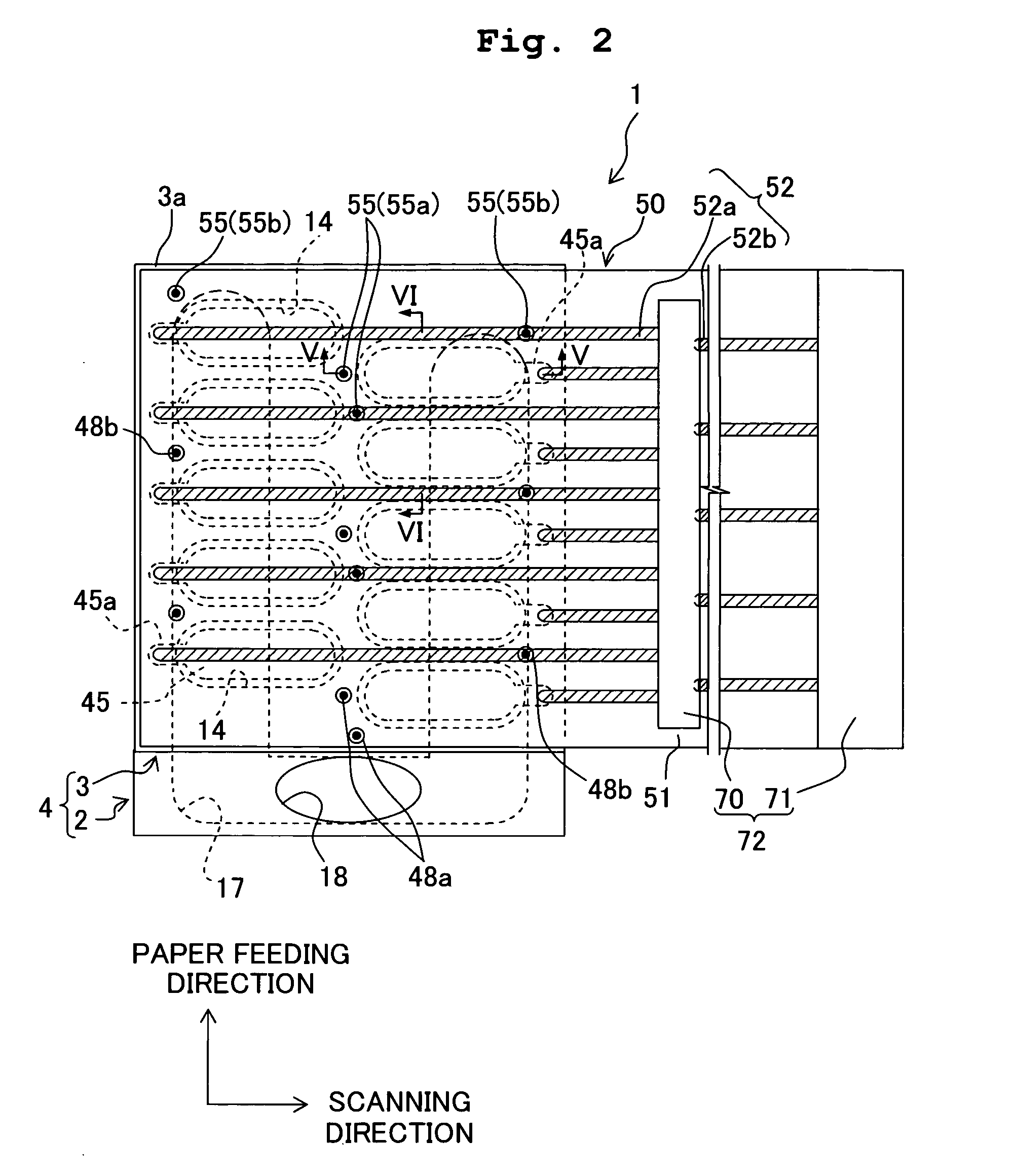
[0035] The projection is in contact with an area of the head body which is different from areas facing the pressure chambers. In this case, since the projection is formed in the flexible flat cable, when the flexible flat cable is connected to the head main body, covering the piezoelectric deformation portions, the flexible flat cable and the piezoelectric deformation portion are isolated from each other, and hardly come in contact. Therefore, since the deformation of the piezoelectric deformation portion, accompanied by a liquid discharge is hardly hindered by the flexible flat cable, it is possible to realize a printer having excellent printing characteristics.

Problems solved by technology

Therefore, at a time of an ink discharge, a deformation of a piezoelectric deformation portion is hindered, and an ink discharge property is declined (deteriorated).

Method used


Image

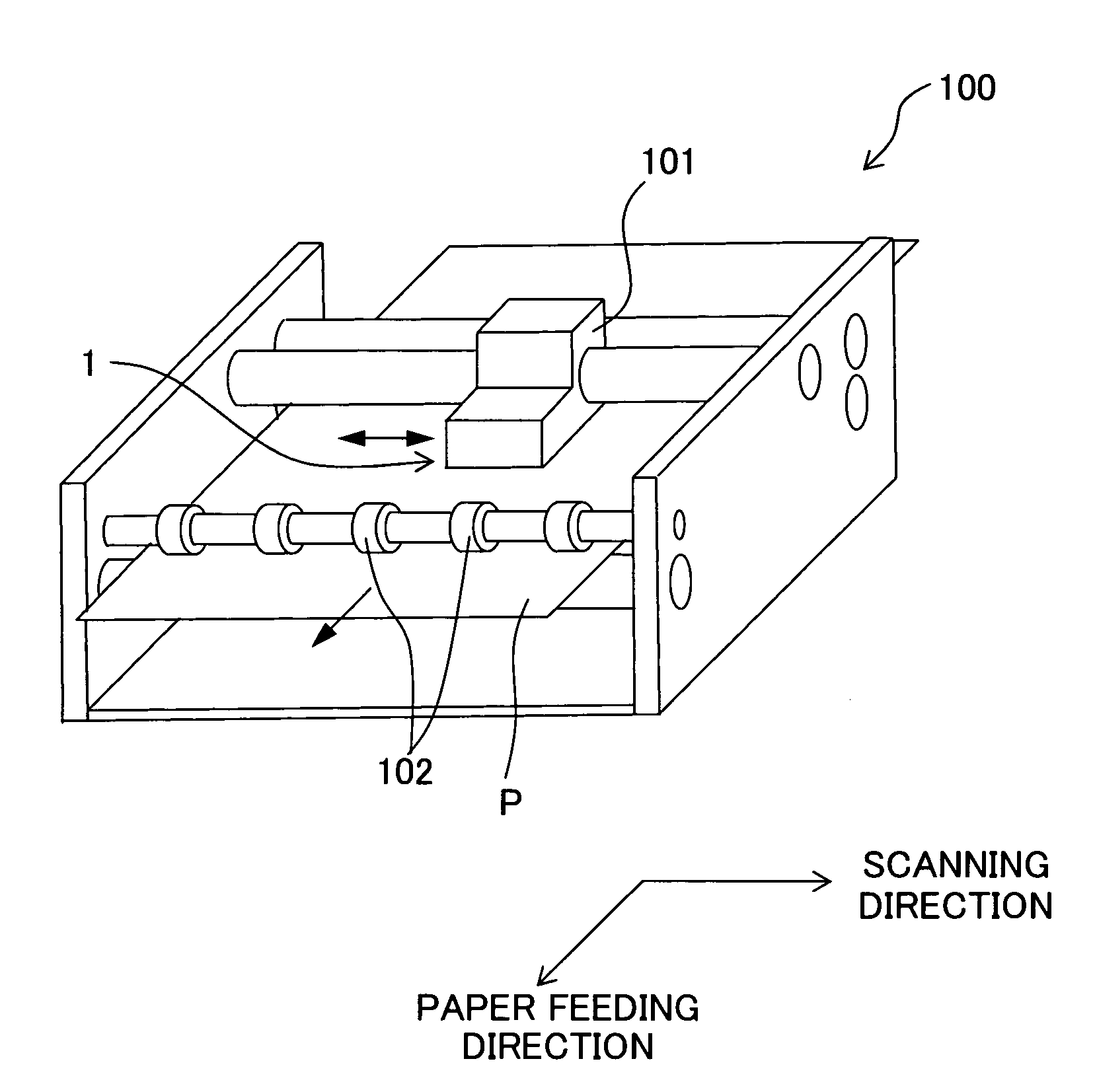
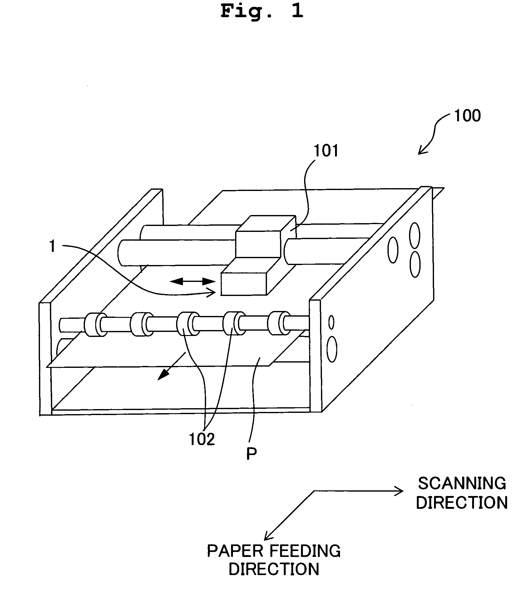
  • Printer, liquid discharging head, and flexible flat cable of liquid discharging head
  • Printer, liquid discharging head, and flexible flat cable of liquid discharging head
  • Printer, liquid discharging head, and flexible flat cable of liquid discharging head

Examples


second embodiment

[0060] Next, an ink-jet head 200 according to a second embodiment will be described below. FIG. 7 is a plan view of the ink-jet head 200 according to the second embodiment. Since components (head main body 4) of the ink-jet head 200, except an FPC 250 are similar to the components in the first embodiment, the same reference numerals are used for these components, and the description of such components is omitted to avoid repetition. The FPC 250 of the ink-jet printer 200, as shown in FIG. 7, includes a substrate 251 similar to the substrate 51, and wires 252 formed on the substrate 251, which is similar to the wires 52. A driver IC 270 is mounted on the substrate 251. The wires 252 include a plurality of individual wires 252a which electrically connect for each individual electrode 45, and the driver IC 270, and a plurality of signal wires 252b which electrically connect the driver IC 270 and a control section (not shown in the diagram). The substrate 251 is a thin plate facing the ...


PUM


Abstract

An ink-jet head includes a head main body including a channel unit in which a pressure chamber is formed, and a piezoelectric actuator having a piezoelectric deformation portion facing the pressure chamber, and an FPC which has a substrate and a plurality of wires, and which is arrange on an upper side of the piezoelectric actuator. A plurality of projections bent to form a projection toward the head main body is formed in the FPC. A front end of the projections is in contact with an area not facing the pressure chamber, on a surface of the piezoelectric actuator. Accordingly, it is possible to suppress hindering of a deformation of the piezoelectric deformation portion accompanied by a liquid discharge, due to a contact with a flexible flat cable.

Description

CROSS REFERENCE TO RELATED APPLICATION [0001] The present application claims priority from Japanese Patent Application No. 2005-219422, filed on Jul. 28, 2005, the disclosure of which is incorporated herein by reference in its entirety. BACKGROUND OF THE INVENTION [0002] 1. Field of the Invention [0003] The present invention relates to a printer which records images by discharging a liquid, a liquid discharging head which discharges a liquid from a liquid discharge port, and a flexible flat cable of the liquid discharging head. [0004] 2. Description of the Related Art [0005] In U.S. patent application Ser. No. 6,979,074, an ink-jet head in which drive electrodes (individual electrodes) are formed in areas of piezoelectric sheets, facing pressure chambers has been disclosed. In this ink-jet head, an actuator unit which is formed by stacking a plurality of piezoelectric sheets is attached to a channel unit in which a large number of nozzles and pressure chambers are formed. Moreover, ...

Claims


Application Information

Patent Timeline
Patent Type & Authority Applications(United States)
IPC IPC(8): B41J2/05B41J2/045
CPCB41J2/14233B41J2202/11B41J2002/14491B41J2002/14266
Inventor KATAYAMA, NAOKI
Owner BROTHER KOGYO KK
Learn More