
Thermal printing head, manufacturing method thereof and thermal printer

A technology of a thermal print head and a manufacturing method, applied in directions such as printing, can solve the problems of electrode short circuit, printing efficiency reduction of printing medium and other printing characteristics, frequent disconnection, etc., and achieve the effect of improving printing characteristics

Pending Publication Date: 2022-04-22
ROHM CO LTD
View PDF2 Cites 0 Cited by
  • Summary
  • Abstract
  • Description
  • Claims
  • Application Information

AI Technical Summary

Problems solved by technology

In order to perform high-speed and high-definition printing, it is important to disperse the heat generated by energization evenly, or to narrow the distance between electrodes (equal to the distance between heating resistors), but when high-speed and high-definition printing is possible In the process of forming electrodes in a thermal print head that performs high-definition printing, since electrodes are integrated at a higher density, short circuits or disconnections of electrodes frequently occur, and there is a possibility that printing characteristics such as printing efficiency on printing media may decrease

Method used


Image

  • Thermal printing head, manufacturing method thereof and thermal printer
  • Thermal printing head, manufacturing method thereof and thermal printer
  • Thermal printing head, manufacturing method thereof and thermal printer

Examples


Embodiment approach 1

[0106] The thermal printhead according to this embodiment will be described with reference to the drawings.

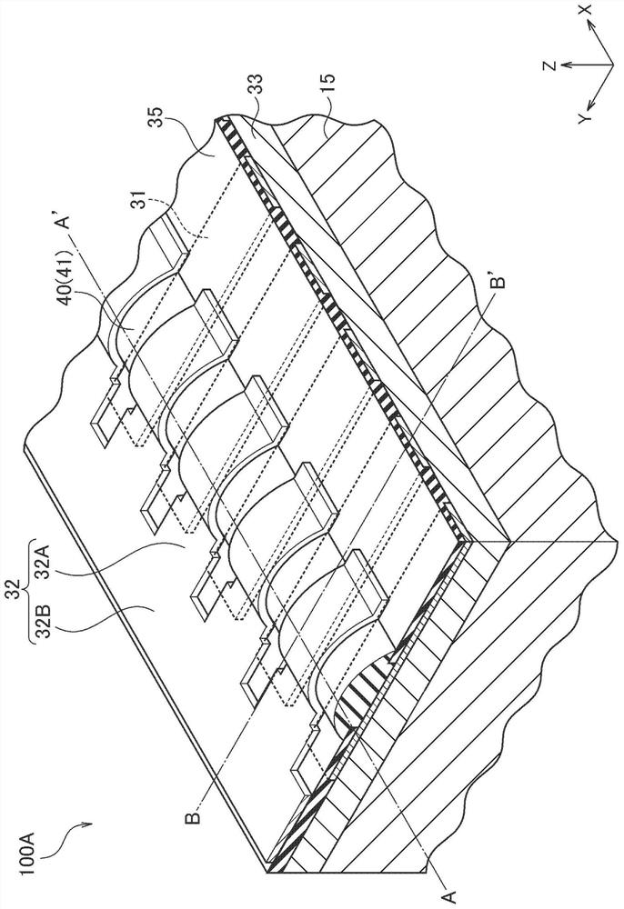
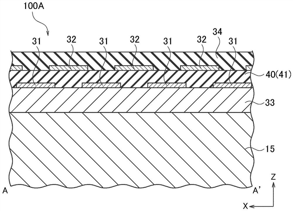
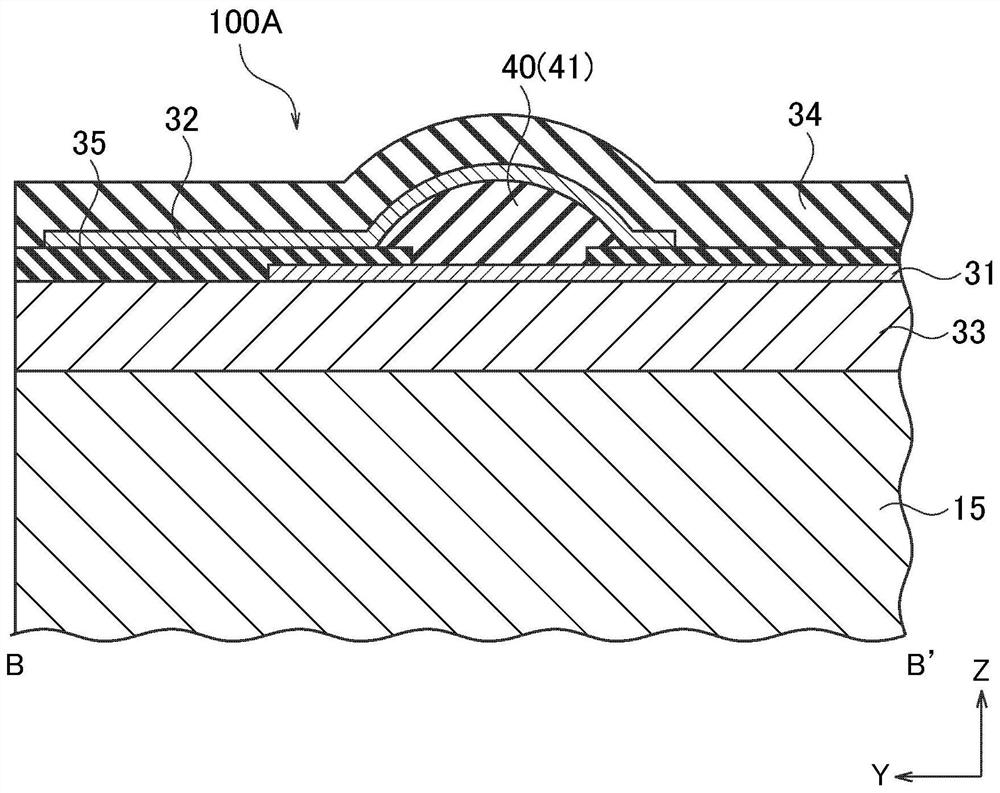
[0107] figure 1 It is a partial perspective view showing a thermal print head. figure 2 is along the main scanning direction X figure 1 A partial sectional view of the A-A' line. image 3 is along the sub-scanning direction Y figure 1 A partial cross-sectional view of the B-B' line. Figure 1 ~ Figure 3A part of the thermal head (corresponding to one thermal head) is shown, and in this embodiment, this one thermal head is a single-chip thermal head 100A. The thermal printhead 100A includes at least a heat storage layer 33 , a first electrode portion on the heat storage layer 33 , a heat generating resistor 40 on the first electrode portion, a second electrode portion on the heat generating resistor 40 , and an electrode covering the second electrode portion. and the protective film 34 of the heating resistor 40 . Specifically, the thermal print head 100A include...

Embodiment approach 2

[0137] The thermal printhead according to this embodiment will be described with reference to the drawings.

[0138] Figure 19 It is a partial perspective view showing a thermal print head. Figure 20 is along the main scanning direction X Figure 19 A partial sectional view of the A-A' line. Figure 21 is along the sub-scanning direction Y Figure 19 A partial cross-sectional view of the B-B' line. Figure 19 ~ Figure 21 A part of the thermal print head (corresponding to one thermal print head) is shown, and in this embodiment, this one thermal print head is a single-chip thermal print head 100B. The thermal printhead 100B includes at least a heat storage layer 33 , a first electrode portion on the heat storage layer 33 , a heat generating resistor 40 on the first electrode portion, a second electrode portion on the heat generating resistor 40 , and an electrode covering the second electrode portion. and the protective film 34 of the heating resistor 40 . Specifically,...


PUM

PropertyMeasurementUnit
sizeaaaaaaaaaa

Abstract

The present invention provides a thermal print head that improves print characteristics with respect to a print medium. In addition, the invention provides a manufacturing method of the thermal printing head. Further, a thermal printer including the thermal print head is provided. The thermal print head of the present invention comprises: a heat storage layer; a first electrode part on the heat storage layer; a heating resistor on the first electrode portion; a second electrode portion on the heating resistor; and a protective film covering the second electrode portion and the heating resistor.

Description

technical field [0001] This embodiment relates to a thermal printhead, a method of manufacturing the same, and a thermal printer. Background technique [0002] In the thermal printhead, for example, a large number of heat generating parts arranged in the main scanning direction are provided on the printhead substrate. Each heat generating portion is formed by stacking a common electrode and an individual electrode on a resistor layer formed on the head substrate with a glaze layer interposed therebetween so that a part of the resistor layer is exposed. The common electrode and the individual electrode ends facing each other. By passing electricity between the common electrode and the individual electrodes, the exposed portion (heating portion) of the resistor layer generates heat due to Joule heat. This heat is transferred to a printing medium (such as heat-sensitive paper used to make a barcode label or a receipt), and printing can be performed on the printing medium. ...

Claims


Application Information

Patent Timeline
Patent Type & Authority Applications(China)
IPC IPC(8): B41J2/335
CPCB41J2/335B41J2/33505B41J2/3359
Inventor 木瀬信和藤田明良
Owner ROHM CO LTD
Learn More