
Image processing apparatus and method therefor

a technology of image processing and image information, applied in the field of image processing apparatus and method, can solve the problems of time and cost, user's hesitation in printing spot colors, and laborious input of contents information,

Inactive Publication Date: 2007-02-01
CANON KK
View PDF10 Cites 46 Cited by
  • Summary
  • Abstract
  • Description
  • Claims
  • Application Information

AI Technical Summary

Benefits of technology

[0008] The second aspect of the present invention discloses an image processing apparatus comprising a processor, arranged to perform image processing for image data in accordance with a combination of color materials including process colors and a spot color, and a generator, arranged to generate a preview image displaying an image area where use of the color material of the spot color is effective when printing is performed with a combination of the color materials of the process colors and the spot color.
[0010] The fourth aspect of the present invention discloses an image processing method comprising the steps of performing image processing for image data in accordance with a combination of color materials including process colors and a spot color, and generating a preview image displaying an image area where use of the color material of the spot color is effective when printing is performed with a combination of the color materials of the process colors and the spot color.
[0011] The present invention can provide the user with information for determining whether or not to print with a combination of color materials including process colors and spot colors.

Problems solved by technology

It is difficult for a user familiar with 4-color printing to recognize improvement of image quality at the expense of time and cost, and the user may hesitate about printing using spot colors.
However, this technique requires labor to input contents information, and an image after printing cannot be confirmed.
In other words, it cannot be confirmed before printing whether improvement of image quality commensurate with the necessary time (labor to input contents information) and cost can be obtained.

Method used


Image

  • Image processing apparatus and method therefor
  • Image processing apparatus and method therefor
  • Image processing apparatus and method therefor

Examples


first embodiment

[Configuration of Image Forming Apparatus]

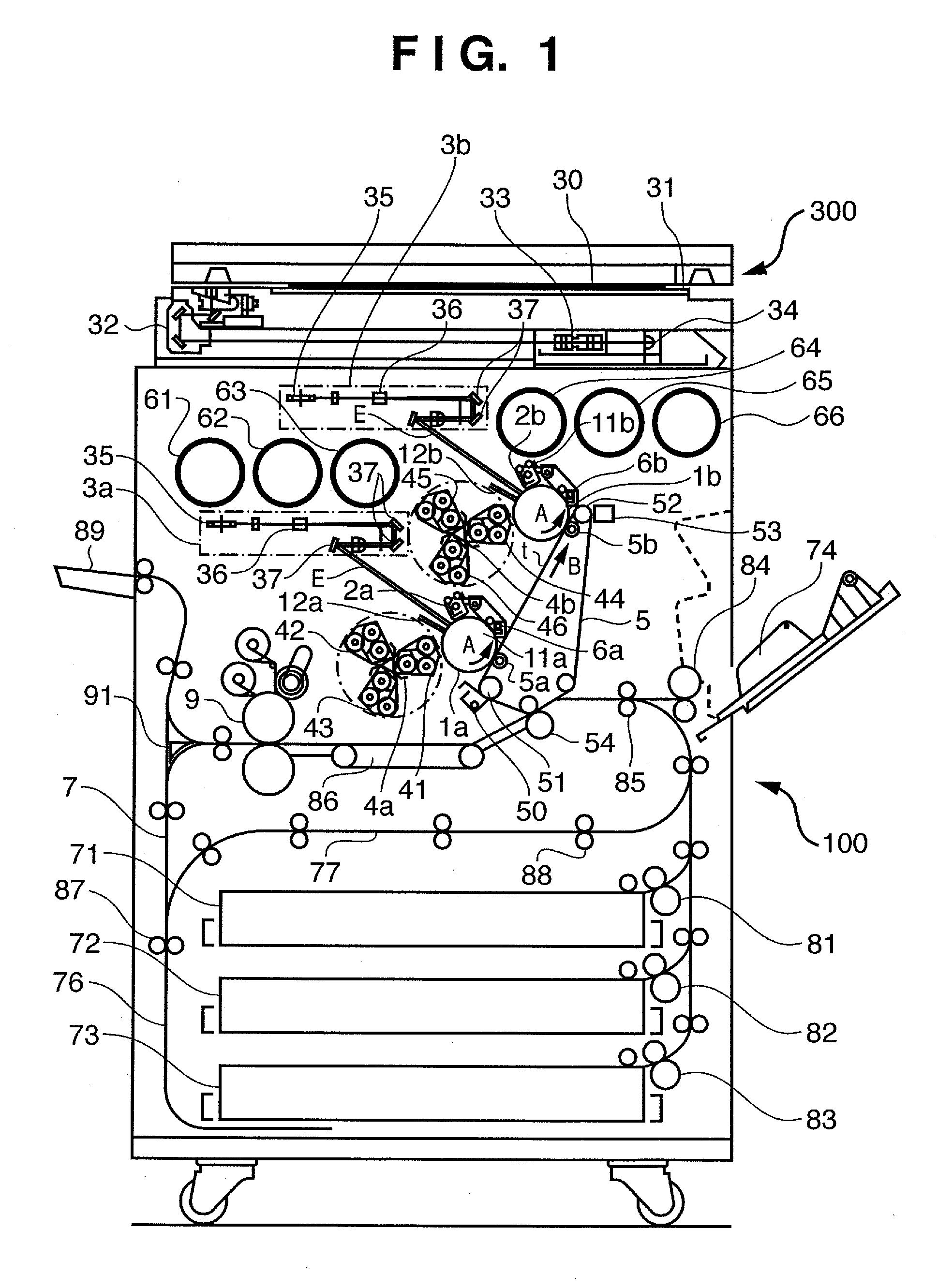
[0032]FIG. 1 is a schematic view showing a full-color image forming apparatus (to be referred to as an image forming apparatus” hereinafter) according to the embodiment.

[0033] The image forming apparatus has a reader 300 as the upper part and a printer 100 as the lower part.

[0034] The reader 300 exposes a document 30 set on a glass document table 31 with light from the lamp of a scanner unit 32, and moves the scanner unit 32 in the sub-scanning direction. Light reflected by the document 30 converges on a CCD sensor 34 via the mirror of the scanner unit 32 and a lens 33. Color-separated image signals output from the CCD sensor 34 are amplified by an amplifier circuit (not shown), and converted into R, G, and B image data by a video processing unit (not shown). The R, G, and B image data are stored in an image memory (not shown), and then output to the printer 100.

[0035] Note that the printer 100 receives image data output from the reader ...

second embodiment

[0095] The image processing apparatus and method according to the second embodiment of the present invention will be explained below. In the second embodiment, the same reference numerals as those in the first embodiment denote the same parts, and a detailed description thereof will be omitted.

[0096] In the second embodiment, not only the high-quality mode recommendation value is displayed, but also a preview image is displayed in the UI, or a sample print is output to visually present the difference between the normal mode and the high-quality mode.

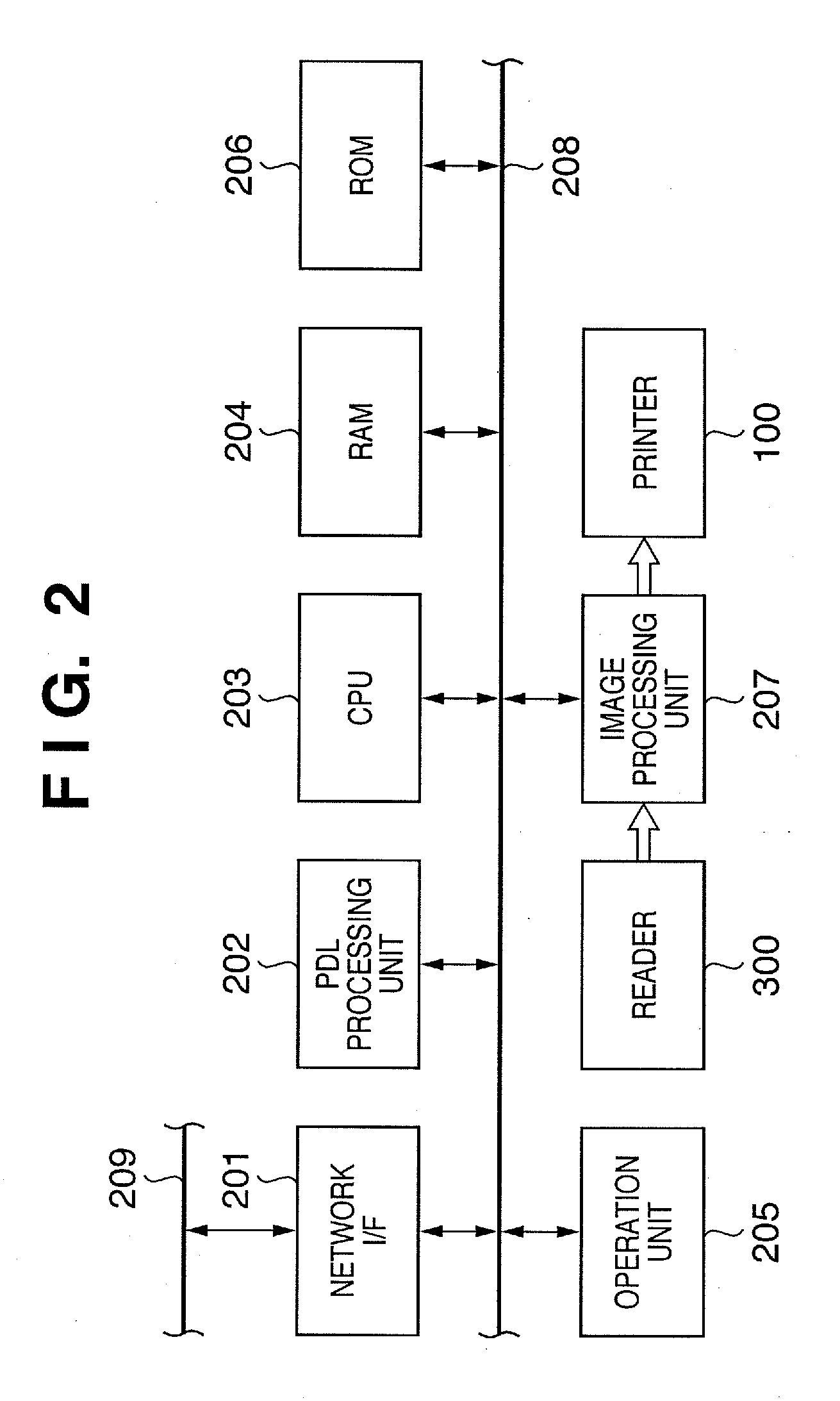
[0097]FIG. 10 is a flowchart showing print mode switching processing executed by a CPU 203 in the second embodiment. Note that steps S1201 to S1205 and S1207 to S1209 are the same processes as those in FIG. 4, and a detailed description thereof will be omitted.

[0098] The CPU 203 determines which of buttons and the print start key in a UI (see FIG. 5) displayed in step S1205 is pressed by the user (S1501). If the user presses a “compar...

third embodiment

[0111] The image processing apparatus and method according to the third embodiment of the present invention will be explained below. In the third embodiment, the same reference numerals as those in the first and second embodiments denote the same parts, and a detailed description thereof will be omitted.

[0112] The third embodiment will explain an example of determining a recommended print mode for images of pages to be printed.

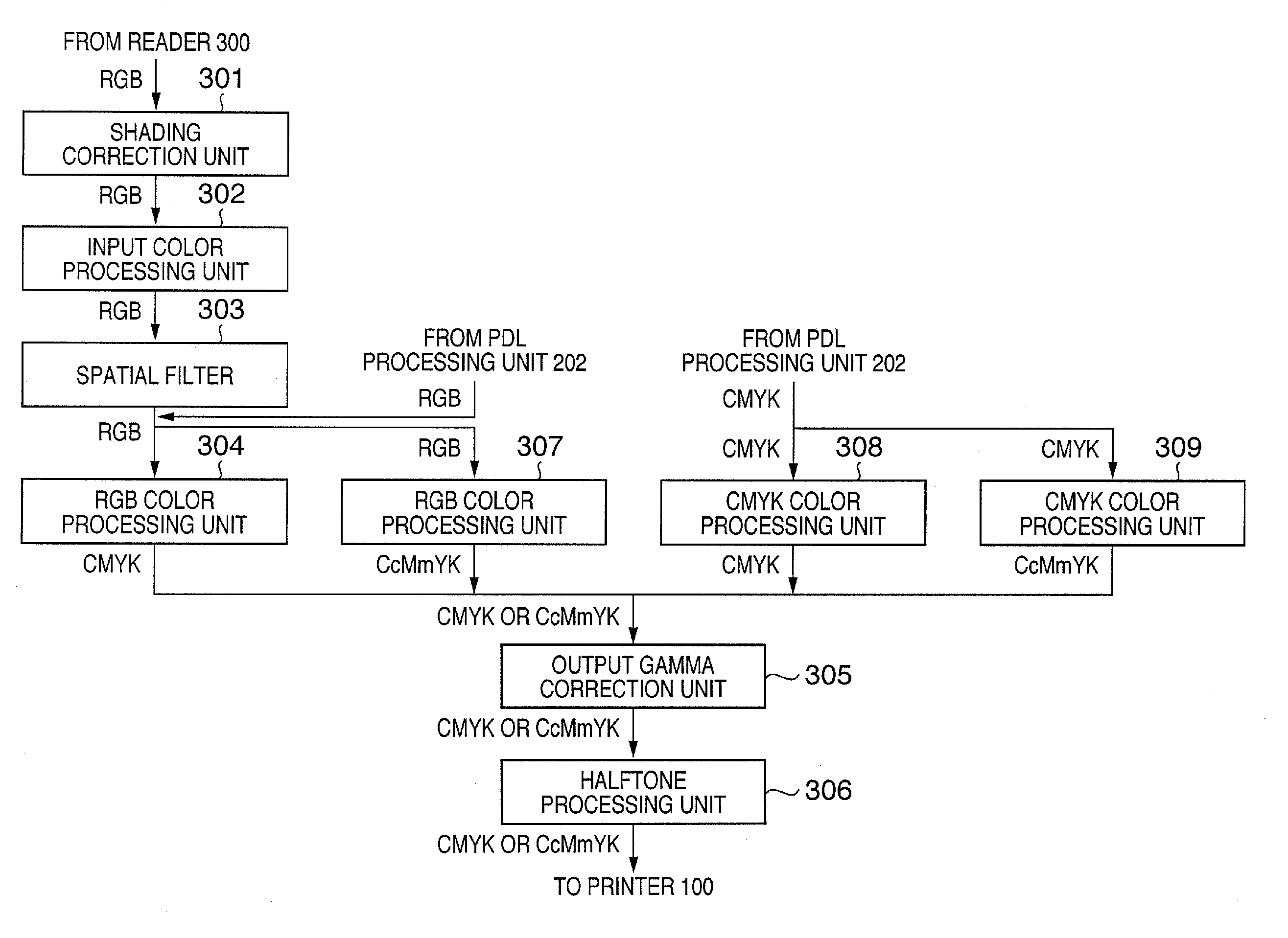
[0113]FIG. 15 is a flowchart showing print mode switching processing executed by a CPU 203 in the third embodiment. Note that details of steps S1201 to S1204, S1502, S1503, and S1208 and S1209 are the same processes as those in FIGS. 4 and 10, and a detailed description thereof will be omitted. Before issuing a print instruction, the user scans the images (images to be printed) of pages by a scanner unit 32, or inputs PDL data of pages (images to be printed) from an external computer. Assume that these scanned images or rendered images are stored in a RAM 20...


PUM


Abstract

There is known a technique of inputting the contents of image data and the use purpose of a print material and automatically selecting a combination of color materials appropriate for them. However, it cannot be confirmed before printing whether improvement of image quality commensurate with the cost and labor to input contents information can be obtained. To solve this problem, the ratio of the amount of the color material of a spot color used to that of the color materials of process colors used in input image data is calculated. The recommendation grade of printing using the spot color is determined on the basis of the ratio. Further, display of the recommendation grade is controlled.

Description

BACKGROUND OF THE INVENTION [0001] 1. Field of the Invention [0002] The present invention relates to an image processing apparatus and method for processing image data in accordance with a combination of color materials including process colors and spot colors. [0003] 2. Description of the Related Art [0004] Recently, printers using the color materials of spot colors in addition to four, cyan, magenta, yellow, and black process colors hit the market, and the user can easily print high-quality images. Types of spot colors are light colors such as light cyan and light magenta which are equal in hue to cyan and magenta and lower in density, metallic colors such as gold and silver, fluorescent colors including a fluorescent material, and a transparent color for adjusting gloss. Effects of using the color materials of spot colors include widening of the gamut, improvement of the gloss and quality, and improvement of the graininess and continuity of tone. Although most of printers additio...

Claims


Application Information

Patent Timeline
IPC IPC(8): H04N1/60
CPCH04N1/54
Inventor SATO, YOKOKATO, SHINICHISAKAUE, TSUTOMUOTAKE, RITSUKOKASHIBUCHI, YOICHI
Owner CANON KK
Learn More