

Laminated electronic component
a technology of electronic components and laminates, applied in the direction of fixed capacitor details, capacitors, capacitors, etc., can solve the problems of inability to predict the shrinkage of the outer portion, the possibility of cracks, and the inability to adjust the shrinkage, so as to prevent the occurrence of cracks and inhibit short-circuit and deterioration in the balance of layer composition
- Summary
- Abstract
- Description
- Claims
- Application Information
AI Technical Summary
Benefits of technology
Problems solved by technology
Method used
Image

Examples
first embodiment
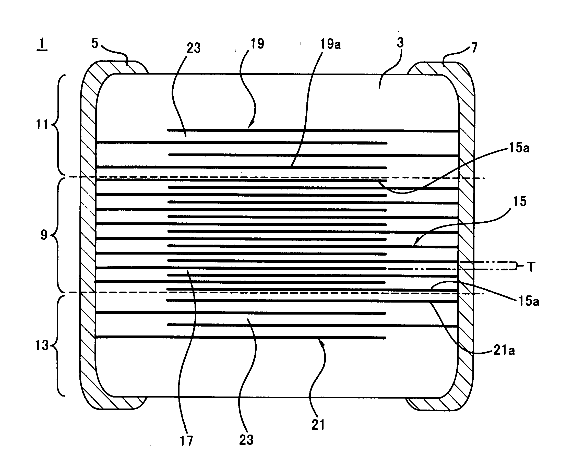
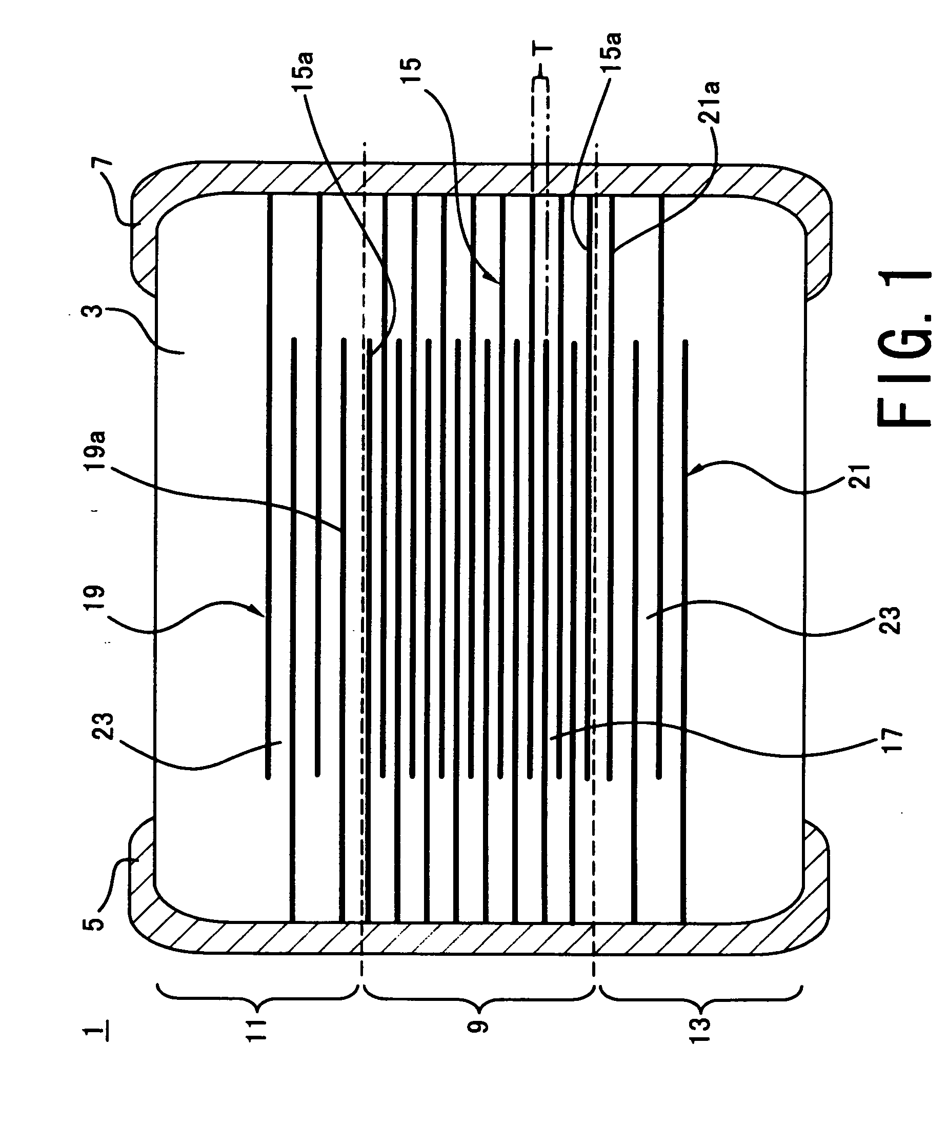
[0038] Referring to the longitudinal sectional view of FIG. 1, a laminated ceramic capacitor 1 according to the present invention comprises a ceramic body 3 and external electrodes 5, 7. The ceramic body 3 has an inner portion 9 and a pair of outer portions 11, 13 disposed above and below the inner portion 9. The external electrodes 5, 7 are disposed on lateral sides of the ceramic body 3.
[0039] The inner portion 9 has a plurality of internal electrodes 15 and dielectric layers 17. On the other hand, the outer portions 11, 13 have a plurality of dummy electrodes 19, 21 and dielectric layers 23. The internal electrodes 15 may be made of any suitable conductive material, for example, mainly of Ni. The dielectric layers 17, 23 may be made of any suitable dielectric material, for example, mainly of ceramic. In this embodiment, the dummy electrodes 19, 21 are made of the same material as the internal electrodes 15.
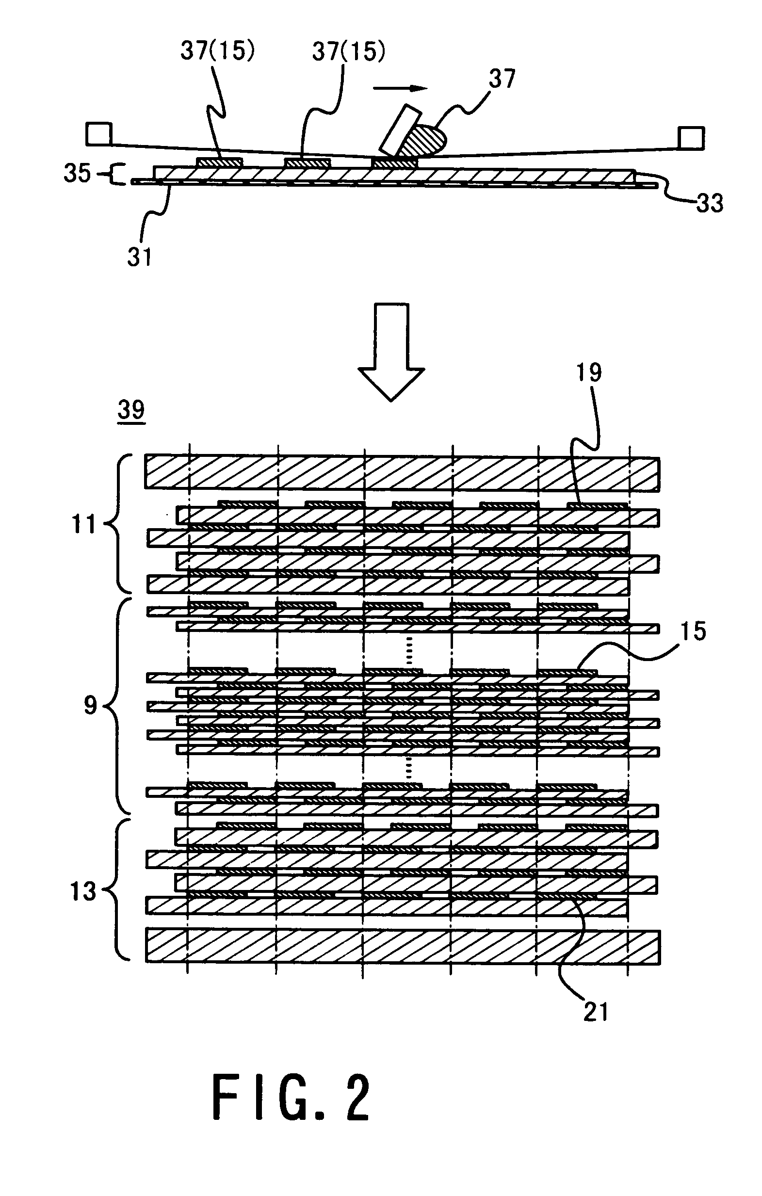
[0040] The process for manufacturing the inner portion 9 will be describe...
second embodiment
[0053] In the second embodiment, four layers of dummy electrodes 19, 21 are embedded in the outer portions 111, 113, respectively. The dummy electrodes 19, 21 are opposed to one another with the dielectric layers 23 therebetween.
[0054] Although there is duplication, the outer portion 111 has one pair of adjacent dummy electrodes (19b, 19c) of opposite polarities and two pairs of adjacent dummy electrodes (19a, 19b) (19c, 19d) of the same polarity. Likewise, although there is duplication, the outer portion 113 has one pair of adjacent dummy electrodes (21b, 21c) of opposite polarities and two pairs of adjacent dummy electrodes (21a, 21b) (21c, 21d) of the same polarity.
[0055] Of the dummy electrodes 19, 21, more particularly, a plurality of layers to be connected to one external electrode are stacked as a unit, and a plurality of layers to be connected to the other external electrode are also stacked as a unit. In FIG. 3, furthermore, the number of layers of the dummy electrodes 19,...
third embodiment
[0059] In the third embodiment, four layers of dummy electrodes 19, 21 are embedded in the outer portions 211, 213, respectively. The dummy electrodes 19, 21 are opposed to one another with the dielectric layers 23 therebetween.
[0060] The distance between adjacent dummy electrodes 19 (21) increases with distance from the inner portion 9. In detail, the dummy electrode 19b (21b) and the dummy electrode 19c (21c) are spaced more than the dummy electrode 19a (21a) and the dummy electrode 19b (21b). In addition the dummy electrode 19c (21c) and the dummy electrode 19d (21d) are spaced more than the dummy electrode 19b (21b) and the dummy electrode 19c (21c) In addition to the advantages described for the laminated ceramic capacitor 1 according to the first embodiment of the present invention, the laminated ceramic capacitor 201 according to the third embodiment of the present invention has another advantage as follows.
[0061] In the outer portions 211, 213, as set forth above, the dista...
PUM
 Abstract
Description
Claims
Application Information