Agitation/deaeration device

a technology of agitation and degasification device, which is applied in the direction of liquid degasification, centrifuges, separation processes, etc., can solve the problems of disadvantageous loss of signal-to-noise ratio of detected signals, hardly applicable in view of cost and size, and disadvantageous loss of signal-to-noise ratio of coupling members

Inactive Publication Date: 2007-02-01
THINKY
View PDF44 Cites 43 Cited by
  • Summary
  • Abstract
  • Description
  • Claims
  • Application Information

AI Technical Summary

Benefits of technology

[0029] Other features and advantageous effects of the present invention will become readily apparent from the embodiments described with reference to accompanying drawings.

Problems solved by technology

However, the use of a standard rotary joint 108a provided at a midpoint in such a coupling member would disadvantageously suffer from a limitation of vacuum level (to an extent of a few torr or so) achieved by reduction in pressure inside the container 109 in which the to-be-kneaded object K is included.
The use of an alternative rotary joint having a special structure such as those which adopt a scheme using a magnetic fluid could carry out agitation / deaeration in a higher degree of vacuum, but would hardly be applicable in view of its cost and size.
Noises that could be produced at the sliding contact, however, would be transmitted too, with the result that a signal-to-noise ratio of the detected signal would disadvantageously decrease.

Method used


Image

  • Agitation/deaeration device
  • Agitation/deaeration device
  • Agitation/deaeration device

Examples


first embodiment

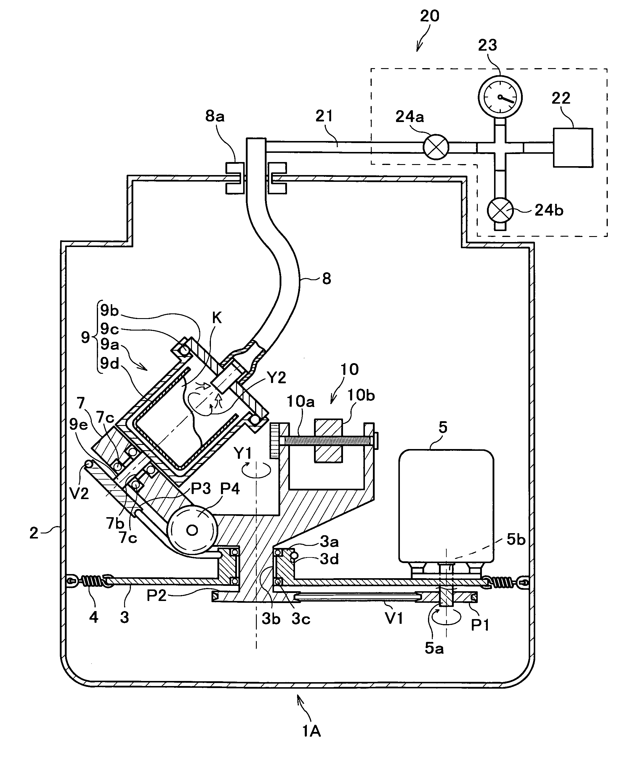
[0037] A detailed description will now be given of the embodiments of the present invention with reference made to the drawings where appropriate. FIG. 1 is a longitudinal section showing an arrangement of an agitation / deaeration apparatus according to the first embodiment.

[0038] As shown in FIG. 1, an agitation / deaeration apparatus 1A includes a housing 2, a support member 3, a motor 5 (first rotation drive mechanism), a revolution table 7, a suction tube 8, a container 9, and a pressure-reduction means 20, and serves to cause the container 9 to make rotations as well as revolutions in a predetermined revolution orbit, so as to agitate and deaerate a to-be-kneaded object K contained in a sample holder 9d which is in turn contained in the container 9.

[0039] The motor 5 is fixed on the support member 3, and has a shaft 5a inserted in a through hole 5b of the support member 3 and protruded down through a bottom surface of the support member 3. A pulley P1 is fixed on a protruded end...

second embodiment

[0067] Referring now to FIG. 4, a second embodiment of the present invention will be described. FIG. 4 is a longitudinal section showing an arrangement of an agitation / deaeration apparatus according to the second embodiment. Features of the agitation / deaeration apparatus 1B according to the second embodiment different from those of the apparatus 1A according to the first embodiment are that there are provided a rotation gear G4, a rotational force application shaft 21 and a rotational force transmission shaft 22 as shown in FIG. 4, instead of the pulley P3, the round-belt groove 3d and the guide pulley P4 as a rotation application mechanism for the container 9 in FIG. 1. In FIG. 4, the same components as in FIG. 1 are designated by the same reference numerals, and a detailed description thereof will not be given hereafter.

[0068] In the second embodiment,“second rotation drive mechanism” as defined in connection with the present invention is comprised of a rotational force applicati...

third embodiment

(Third Embodiment)

[0075] Referring now to FIG. 5, a third embodiment of the present invention will be described. FIG. 5 is a longitudinal section showing an arrangement of an agitation / deaeration apparatus according to the third embodiment. In FIG. 5, parts substantially the same as those in FIG. 1 are designated by the same reference characters with a prime symbol (′) or dash mark affixed thereto, and a detailed description thereof will be omitted hereafter.

[0076] An agitation / deaeration apparatus 1C according to the third embodiment includes a revolution table 7′ on which a container 9′ is supported rotatably about a support shaft 9e through rotary bearings 7c, a motor 5′ (first rotation drive mechanism) configured to drive and rotate the revolution table 7′, a supply device 45, a collection device 46, a coupling member 42, and a thermoregulator 47. In this arrangement, the to-be-kneaded object K can be supplied to and the kneaded object K can be collected from the inside of the ...


PUM

PropertyMeasurementUnit
pressureaaaaaaaaaa
torsional rigidityaaaaaaaaaa
rotational speedaaaaaaaaaa

Abstract

An agitation / deaeration apparatus is provided which causes a container containing a viscous to-be-kneaded object to be rotated and revolved simultaneously, to agitate and deaerate the to-be-kneaded object, wherein piping (wiring) connecting the container and an external device is prevented from twisting even when the container rotates. In an agitation / deaeration apparatus (1A) which performs agitation and deaeration of a to-be-kneaded object (K) by causing a container (9) accommodating a to-be-kneaded object (K) to be rotated about a rotation axis (Y2) of the container (9) and revolved about a revolution axis (Y2), provided are: a first rotation drive mechanism (motor 5) configured to drive and rotate a revolution table (7); a second rotation drive mechanism (a round-belt groove 3d, a pulley P3) configured to rotate the container (9) in a reverse direction at the same rotational speed relative to the revolution table (7); one or more of distribution means (a suction tube 8) of which one end is connected with the container (9) and the other end is connected with the external device.

Description

TECHNICAL FIELD [0001] This invention relates to an agitation / deaeration apparatus which revolves, and rotates at the same time, a container accommodating viscous fluid materials, such as a solder paste, an impression material for dentistry, and a liquid crystal material (hereinafter referred to as“to-be-kneaded object”), and thereby agitates and deaerates the to-be-kneaded object, and more particularly to an agitation / deaeration apparatus in which a container to be rotated is connected with an external device through wiring or piping. BACKGROUND ART [0002] An agitation / deaeration apparatus in which a container containing a to-be-kneaded object is revolved, and rotated in a revolution orbit, has been hitherto known in the art. [0003] This type of the agitation / deaeration apparatus is configured to press a to-be-kneaded object against an interior wall of the container centrifugally by the action of revolution of the container, thus releasing bubbles incorporated in the to-be-kneaded ...

Claims


Application Information

Patent Timeline
Patent Type & Authority Applications(United States)
IPC IPC(8): B01F9/22B01F13/06B01F15/06B01F29/90B01D19/00B01F23/47B01F29/60H05K3/34
CPCB01D19/0052B01F3/10H05K3/3484B01F13/06B01F9/0001B29B7/106B29B7/845H05K3/3485B01F23/47B01F29/10B01F33/70
Inventor ISHII, HIROSHIGE
Owner THINKY
Why Eureka
Try Eureka