

Method and apparatus for data signal processing in wireless RFID systems
a technology of wireless rfid and data signal processing, applied in the field of wireless telecommunications equipment, systems and methods, can solve the problems of multipath propagation, fast fading, and severe interference of rfid communication channels
- Summary
- Abstract
- Description
- Claims
- Application Information
AI Technical Summary
Problems solved by technology
Method used
Image

Examples
example rfid system embodiment
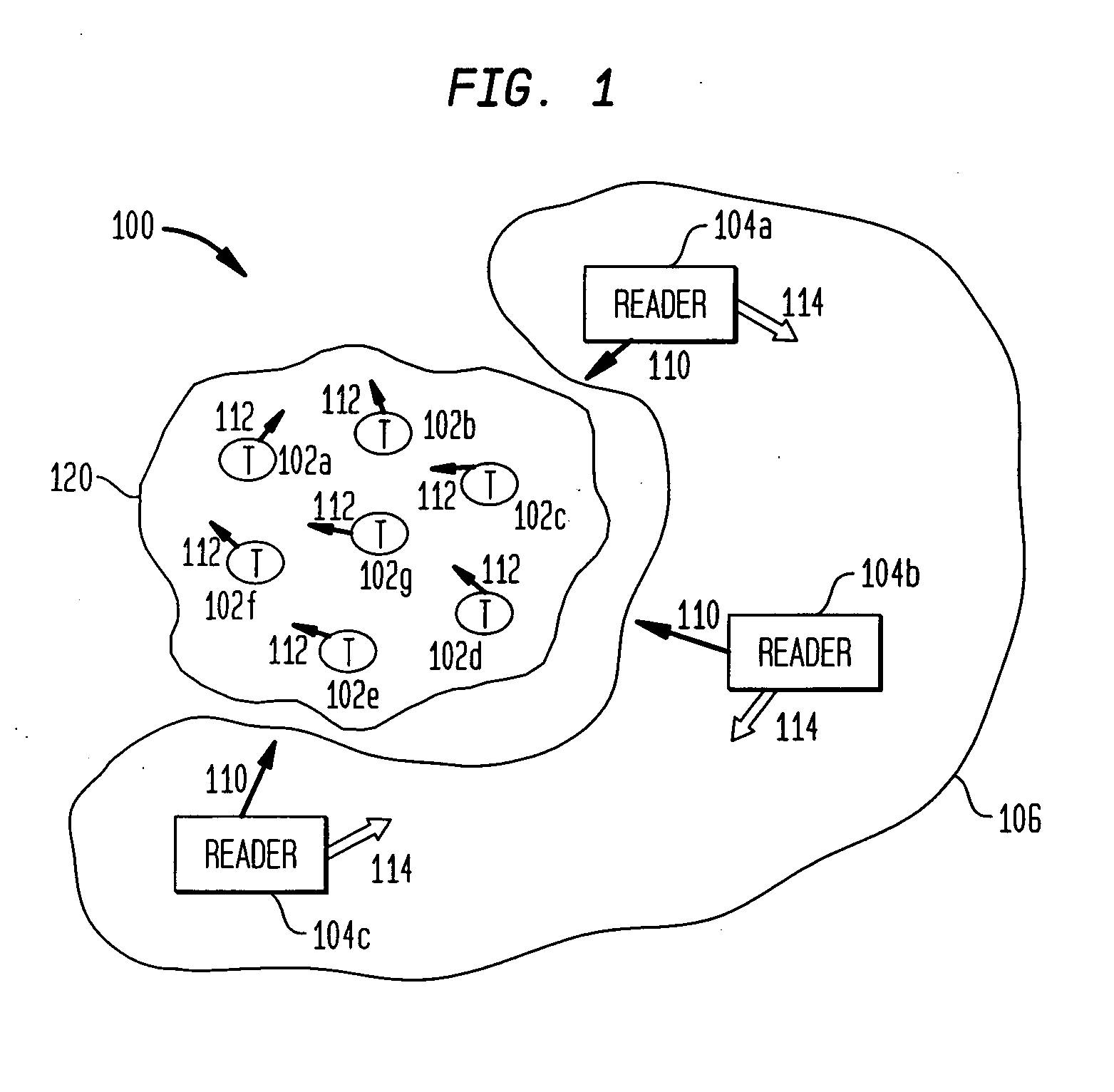
[0037] Before describing embodiments of the present invention in detail, it is helpful to describe an example RFID communications environment in which the invention may be implemented. FIG. 1 illustrates an environment 100 where RFID tag readers 104 communicate with an exemplary population 120 of RFID tags 102. As shown in FIG. 1, the population 120 of tags includes seven tags 102a-102g. According to embodiments of the present invention, a population 120 may include any number of tags 102.
[0038] Environment 100 includes either a single reader 104 or a plurality of readers 104, such as readers 104a-104c. In an embodiment, a reader 104 may be requested by an external application to address the population of tags 120. Alternatively, reader 104 may have internal logic that initiates communication, or may have a trigger mechanism that an operator of reader 104a uses to initiate communication.
[0039] As shown in FIG. 1, readers 104 transmit an interrogation signal 110 having a carrier fr...
reader embodiment
Example Conventional RFID Reader Embodiment
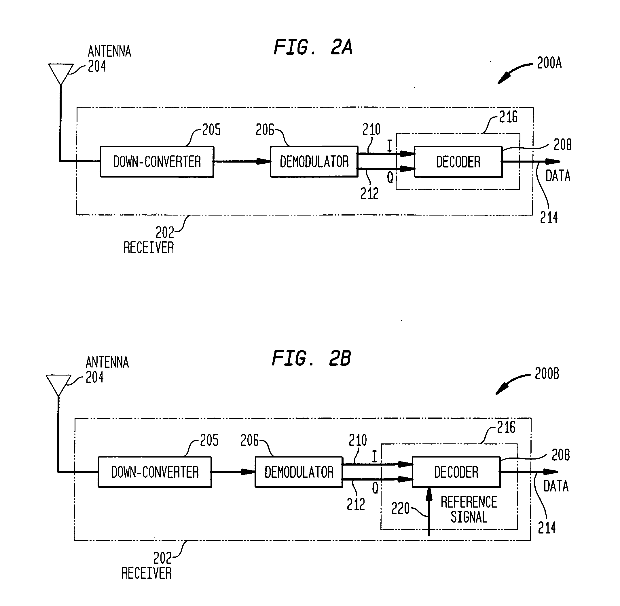
[0043]FIG. 2A shows an example block diagram of the receiver portion of a conventional RFID reader 200A. Reader 200A typically includes one or more antennas 204, one or more receivers 202, one or more transmitters, one or more memory units, and one or more processors (transmitters, memory units, and processors are not shown in FIG. 2A). As shown in the example of FIG. 2A, receiver 202 includes a frequency down-converter 205, a demodulator 206, and a decoder 208. These components of reader 200A may include software, hardware, and / or firmware, or any combination thereof, for performing their functions, which are described in further detail in subsequent sections herein.
[0044] Reader 200A has at least one antenna 204 for communicating with tags 102 and / or other readers 104. In an example FCC environment, interrogator transmission and tag responses are spectrally separated. Typically, an interrogator sends an interrogation signal at higher fre...
example apparatus embodiments
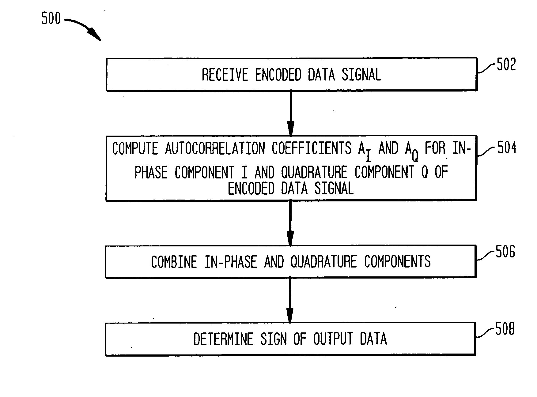
[0062]FIG. 6 shows the base-band portion 600 of a receiver used in wireless communication system, configured to execute the steps of the autocorrelation algorithm described by flowchart 500. As shown in FIG. 6, base-band portion 600 includes first and second delay modules 620a and 620b, first and second multipliers 630a and 630b, an integrator 640, a synchronization module 639, and a decision module 650.
[0063] As shown in FIG. 6, first delay module 620 a receives an in-phase signal component 610 and outputs a delayed in-phase signal component 611. Second delay module 620b receives a quadrature signal component 612 and outputs a delayed quadrature signal component 613. First and second delay modules 620a and 620b respectively delay their input signals by a known amount. For example, first and second delay modules 620a and 620b may delay their respective input signals by an amount based on a length of a tag data symbol (i.e., a “tag symbol interval”) having a length T, such as a dela...
PUM
 Abstract
Description
Claims
Application Information