Transmitter of a System for Detecting a Buried Conductor

a technology of buried conductor and transmitter, which is applied in the direction of pulse automatic control, reradiation, amplifier, etc., can solve the problems of difficult to detect the target buried conductor, damage to the transmitter, and the control law used does not allow the transmitter to react quickly to changes in load

Active Publication Date: 2010-01-07
RADIODETECTION
View PDF8 Cites 28 Cited by
  • Summary
  • Abstract
  • Description
  • Claims
  • Application Information

AI Technical Summary

Benefits of technology

[0027]The feedback voltage and current of the output signal may be filtered through a narrow band filter. The narrowband filter may have a bandwidth of less than 100 Hz, preferably less than 75 Hz and preferably less than 40 Hz.

Problems solved by technology

In addition, a high power signal can couple to unwanted lines and spread over the lines, making it difficult to detect the target buried conductor.
A problem with conventional signal transmitters is that the transmitter performs poorly in response to a change in the load, which can lead to damage to the transmitter.
Although conventional signal transmitters comprise a basic feedback loop to stabilise the signal output from the transmitter, the control law used does not allow the transmitter to react quickly to changes in the load.
For example, sudden disconnection of the load may not be expediently detected by the transmitter, resulting in driving the amplifiers too hard and potentially damaging the transmitter.
In addition, the feedback loop can detect and process ambient signals and inefficiently drive amplifiers in the transmitter based on the ambient signals.

Method used


Image

  • Transmitter of a System for Detecting a Buried Conductor
  • Transmitter of a System for Detecting a Buried Conductor
  • Transmitter of a System for Detecting a Buried Conductor

Examples


Embodiment Construction

[0045]The invention will now be described with reference to the drawing figures, in which like reference numerals refer to like parts throughout.

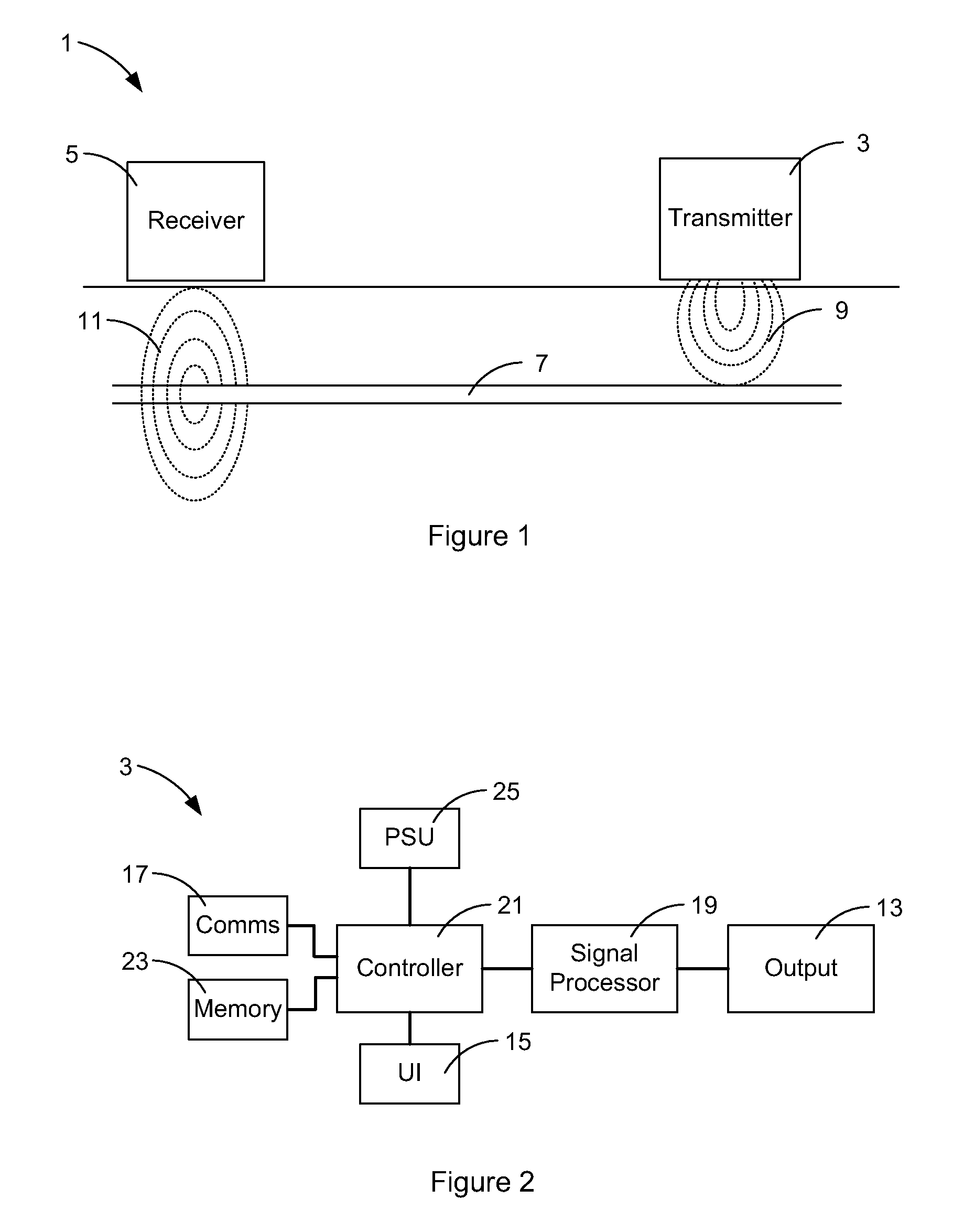
[0046]FIG. 1 is a schematic representation of a system 1 for detecting a buried conductor according to an embodiment of the invention, comprising a portable transmitter 3 and a portable receiver 5. The transmitter 3 is placed in proximity to a buried conductor 7 to produce an alternating current test signal in the buried conductor 7.

[0047]An aerial in the transmitter 3 is fed with an AC voltage to produce an electromagnetic field 9 which links around the buried conductor 7, thereby inducing the alternating current test signal in the buried conductor 7. The alternating current test signal is radiated as an electromagnetic field 11 by the buried conductor 7 and this electromagnetic field can be detected by the receiver 5. In other embodiments the transmitter may provide a test signal in the conductor by direct connection to the conductor or b...


PUM


Abstract

A system for detecting a buried conductor comprises a transmitter for generating a test signal in the buried conductor and a detector for detecting an electromagnetic signal resulting from the test signal flowing in the buried conductor. The transmitter comprises a waveform generator for generating a drive waveform signal, a power supply, an amplifier, connected to the power supply and the waveform generator for producing an output drive signal based on the drive waveform signal and an output circuit for acting on the output drive signal to generate an output signal having a current and a voltage. In-phase and quadrature components of the current and voltage of the output signal are fed back for controlling the amplifier.

Description

CROSS REFERENCE TO RELATED APPLICATIONS[0001]This application claims priority to United Kingdom Patent Application GB 0803871.3, filed on Feb. 29, 2008, and entitled “Transmitter of a System for Detecting a Buried Conductor,” the disclosure of which is incorporated herein by reference in its entirety.FIELD OF THE INVENTION[0002]The present invention relates to a transmitter of a system and method for detecting a buried conductor.BACKGROUND OF THE INVENTION[0003]Before commencing excavation or other work where electrical cables, fibre optic cables or other utilities ducts or pipes are buried, it is important to determine the location of such buried cables or pipes to ensure that they are not damaged during the work. Once a buried utility is located the depth of the utility can be calculated to determine a safe excavation depth.[0004]Current carrying conductors emit electromagnetic radiation which can be detected by an electrical antenna. If fibre optic cables or non-metallic utilitie...

Claims


Application Information

Patent Timeline
Patent Type & Authority Applications(United States)
IPC IPC(8): G01V3/08H03L5/00
CPCG01V3/081H03F3/211H03F2200/432H03F3/24H03F3/2173G01R29/085G06F1/022
Inventor ROYLE, JOHN MARKPEARSON, RICHARD DAVID
Owner RADIODETECTION
Why Eureka
Try Eureka