
Power regulator for power inverter

a technology of power regulator and inverter, which is applied in the direction of process and machine control, electric generator control, electric devices, etc., can solve the problems of inverter hazard, undiscovered island standing, and remaining energized at potentially hazardous levels

Active Publication Date: 2005-03-17
SQUARE D CO
View PDF19 Cites 28 Cited by
  • Summary
  • Abstract
  • Description
  • Claims
  • Application Information

AI Technical Summary

Benefits of technology

The present invention comprises a method and apparatus to regulate a power inverter. In an exemplary embodiment, a method of controlling the real and reactive power output by the inverter comprises calculating x-y phasor components of inverter output current and voltage referenced to a desired x-y coordinate frame and measuring real and reactive power output by the inverter based on the calculated x-y phasor components. The inverter's output current and voltage thus are indirectly adjusted by reducing a difference between the measured and desired real powers and the measured and desired reactive powers. Calculation of the x-y phasor components can be based on integrating over half-cycles of the voltage and current waveforms for single-phase inverter applications.

Problems solved by technology

Grid-connected inverters pose certain hazards, with undetected islanding standing as a primary hazard.
With islanding, a portion of the utility grid becomes disconnected from or otherwise isolated from the rest of the grid but remains energized at potentially hazardous levels because of its connection to one or more local power inverters.
Unless the connected power inverters recognize the islanding condition, the isolated portion of the grid remains energized even if other parts of the grid are de-energized, creating a potentially hazardous condition for service personnel and others.

Method used


Image

  • Power regulator for power inverter
  • Power regulator for power inverter
  • Power regulator for power inverter

Examples


Embodiment Construction

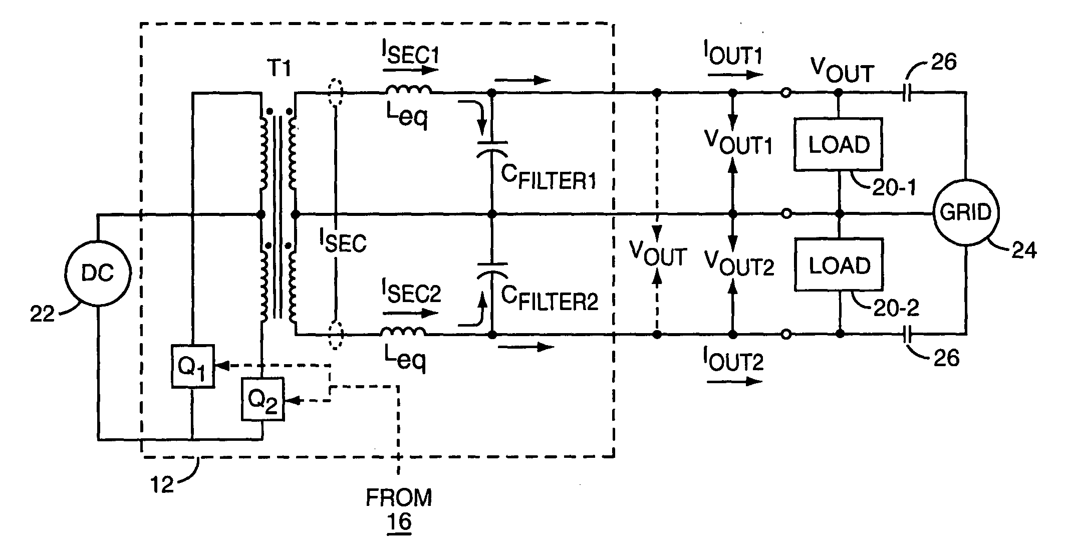
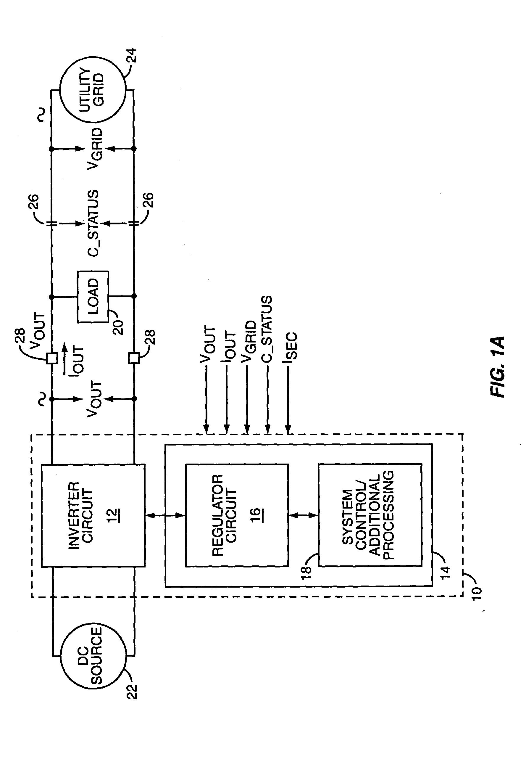
FIG. 1A illustrates an exemplary ac power inverter 10 in which the present invention can be practiced. Inverter 10 comprises an inverter circuit 12 and a control circuit 14, which can include multiple functional circuits, including a regulator circuit 16, and one or more additional processing and system control circuits 18.

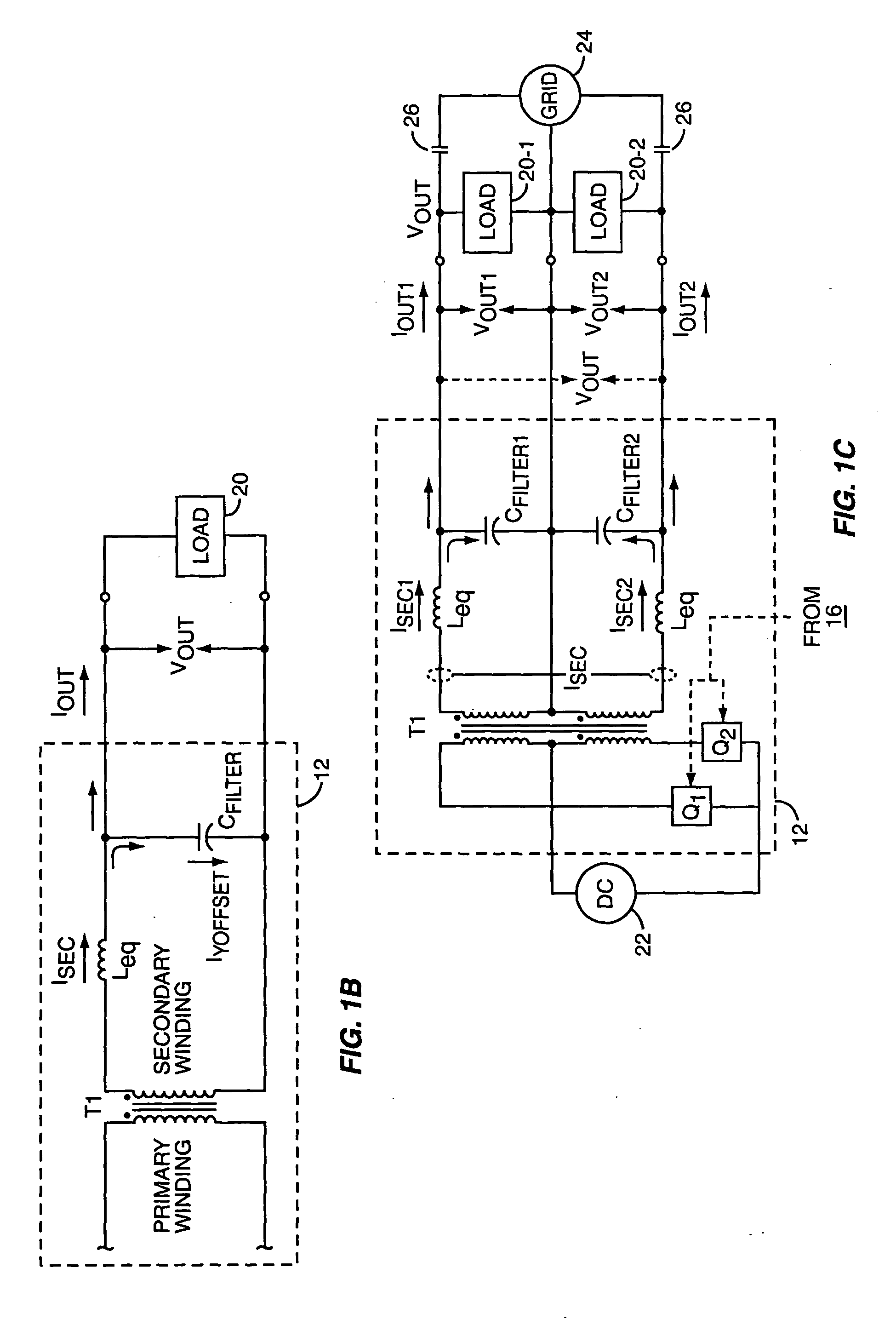
Inverter 10 provides ac power to a load 20 based on converting dc power provided by a local dc source 22 into ac power at the desired voltage and frequency. The load 20 can be connected in parallel with an external power system 24, e.g., a utility grid, through contactors 26. Complementing its operation in this arrangement, inverter 10 can be configured to receive a number of feedback / detection signals, including signals corresponding to its output voltage (VOUT) and current (IOUT), the grid voltage (VGRID), the contactor status (C_STATUS), and to a secondary winding current (ISEC) that is illustrated in FIG. 1B.

FIG. 1B does not depict the entire inverter circui...


PUM


Abstract

A power inverter includes a regulator circuit that controls real and reactive power output by the inverter. The regulator measures real and reactive output power by calculating x-phasor components of the inverter's voltage and current output waveforms. Phasor calculation can be adapted for one or more pairs of single-phase voltages and currents. Determining the fundamental in-phase and quadrature components of output voltage and current reduces computational complexity by permitting the regulator to perform its power control processing largely in a dc signal domain, and enables separate real and reactive power control. The power inverter can include islanding detection logic, which exploits the ability to separately control reactive power. Exemplary islanding detection logic is based on determining whether changing the amount of reactive power output by the inverter induces an output frequency shift.

Description

BACKGROUND OF THE INVENTION The present invention generally relates to ac power control, and particularly relates to power regulation for ac power inverters. Increasing use of localized power sources in residential and industrial settings coincides with the increasing desire to exploit potentially cheaper, cleaner, or more reliable alternative energy sources. Historically, individuals and businesses relied on central generation stations with power transmission and distribution networks, i.e., the traditional “grid,” almost exclusively but the developing trend is toward a number of smaller generating units, distributed geographically close to the loads. Local power generation using power sources such as photovoltaic systems, fuel cells, etc., also is becoming a viable option for businesses and homeowners. These local power generating systems can be configured as stand-alone systems that operate as the exclusive source of power for their local loads or they can be interconnected wit...

Claims


Application Information

Patent Timeline
IPC IPC(8): H02J3/18H02J3/48H02M7/538
CPCH02J3/1835H02J3/48Y02E40/30H02M7/53803H02J2003/388H02J3/388
Inventor COLBY, ROY STEPHENKOCHER, MARK JOHNCARSON, GERALD BENJAMIN
Owner SQUARE D CO
Learn More