

Automatic frequency control loop circuit
a loop circuit and automatic technology, applied in automatic frequency control, digital transmission, pulse automatic control, etc., can solve the problems of time information error in the baseband, time information error, and the inability of the receiving part to process the received signal exactly
- Summary
- Abstract
- Description
- Claims
- Application Information
AI Technical Summary
Benefits of technology
Problems solved by technology
Method used
Image

Examples
first embodiment
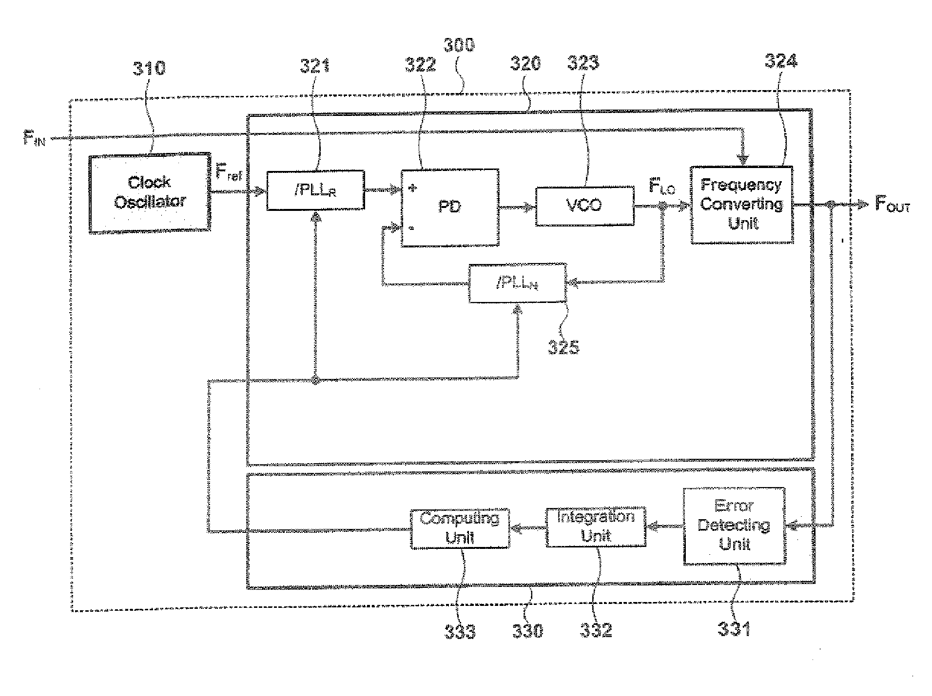
[0051]FIG. 3 is a block view illustrating a receiver that can oscillate a frequency in a broadband in accordance with an embodiment of the present invention.
[0052] As shown in FIG. 3, the receiver 300 comprises a clock oscillator 310, a frequency synthesizer 320, and a demodulator 330. The clock oscillator 310 comprises a device for oscillating a reference frequency Fref. The frequency synthesizer 320 receives the reference frequency Fref, an input frequency FIN, and a control signal for compensating an output frequency FOUT. The demodulator 330 detects error of the output frequency FOUT in the frequency synthesizer 320, and inputs the control signal for compensating for the detected error to the frequency synthesizer 320.
[0053] The clock oscillator 310 comprises an oscillation device for oscillating the reference frequency Fref. The frequency synthesizer 320 comprises a first dividing unit 321, a second dividing unit 325, a phase detecting unit 322, a voltage-controlled oscillati...
second embodiment
[0065]FIG. 4 is a block view describing a receiver that can oscillate a frequency in a broadband in accordance with another embodiment of the present invention.
[0066] As illustrated in FIG. 4, the receiver 400 comprises a clock oscillator 410, a frequency synthesizer 420, and a demodulator 430. The clock oscillator 410 comprises a device for oscillating a reference frequency Fref. The frequency synthesizer 420 receives the reference frequency Fref, an input frequency FIN, and a control signal for compensating an output frequency FOUT. The demodulator 430 detects an error of the output frequency FOUT oscillated in the frequency synthesizer 420, and inputs a control signal for compensating for the detected error to the frequency synthesizer 420.
[0067] The clock oscillator 410 comprises a device for oscillating a reference frequency Fref. The frequency synthesizer 420 comprises a first dividing unit 421, a second dividing unit 425, a phase detecting unit 422, a voltage-controlled osc...
third embodiment
[0082]FIG. 5 is a block view showing a receiver that can oscillate a frequency in a broadband in accordance with yet another embodiment of the present invention.
[0083] As illustrated in FIG. 5, the receiver 500 comprises a clock oscillator 510, a frequency synthesizer 520, and a demodulator 530. The clock oscillator 510 comprises a device for oscillating a reference frequency Fref. The frequency synthesizer 520 receives the reference frequency Fref, an input frequency FIN, and a control signal for compensating an output frequency FOUT. The demodulator 530 detects an error of the output frequency FOUT in the frequency synthesizer 520, and inputs the control signal for compensating for the detected error to the frequency synthesizer 520.
[0084] The clock oscillator 510 comprises a device for oscillating a reference frequency Fref. The frequency synthesizer 520 comprises a first dividing unit 521, a second dividing unit 525, a phase detecting unit 522, a voltage controlled oscillating...
PUM
 Abstract
Description
Claims
Application Information