Supercharge Your Innovation With Domain-Expert AI Agents!

Image encoding method and image encoder, image decoding method and image decoder, and image processing system

a technology of image encoding and encoder, applied in the field of image encoding method and image encoder, image decoding method and image decoder, image processing system, can solve the problems of inability to reconstruct important bases to intrinsic signal representations, dct has the tendency to notice the distortion caused by quantization in the boundary of blocks, and coarse quantization degrades a reconstruction of coefficients. to achieve the effect of improving the efficiency of total coding

Inactive Publication Date: 2007-02-01
NTT DOCOMO INC
View PDF1 Cites 18 Cited by
  • Summary
  • Abstract
  • Description
  • Claims
  • Application Information

AI Technical Summary

Benefits of technology

[0011] It is a first object of the present invention to provide a method and an apparatus that improve total coding efficiency by compactly representing encoded data by means of the pattern matching technique.
[0018] When the number of points at which it is determined whether or not the partial waveform signal and the waveform vector match are decreased, it becomes possible to reduce the number of operations. From the viewpoint, as claimed in claim 3, in the above-mentioned pattern matching step, pixels formed of a predetermined power of 2×2 of an image signal represented by a predetermined pixel unit may be set as a unit, and a position in an image of a partial signal waveform to be encoded may be identified.
[0024] According to such an image encoding method, a group of waveform vectors to be used is selected among a plurality of groups of waveform vectors based upon the parameter used for performing an encoding at the first image encoding step and the position in the second image of the partial waveform signal. As a result, it is possible to select a group of waveform vectors corresponding to a characteristic of each image to be encoded and to encode the image signal more appropriately.
[0025] The second image information is a signal corresponding to an error signal between a first image signal provided to the first encoding step and a signal obtained by performing a local decoding process for encoding information obtained at the first image encoding step. As a result, when the first image information provided to the first image encoding step is assumed to be a source image, the second image information corresponds to an encoding distortion signal generated by encoding the source image. In such a case, according to the image encoding method, it is possible to efficiently encode a signal corresponding to the error signal ending up with unnecessary additional information when the source image is encoded.

Problems solved by technology

On the other hand, when encoding is performed at an extremely low bit rate, a resulting coarse quantization degrades a reconstruction of the coefficients.
Consequently, there arise some problems in that it is impossible to reconstruct important bases to an intrinsic signal representation.
Also, since the DCT operates a closed process on an 8×8 image block, the DCT has the tendency that a distortion caused by quantization noticeably appears in a boundary of blocks.
That generates a block distortion and exhibits in the image an element that the original signal does not contain visually, whereby the element is recognized as a seriously noticeable noise.
As a result, the coefficient in the high frequency, which plays an important role in reconstructing the waveform, is lost.
The loss of the coefficient causes harmful noise peculiar to the DCT and results in image quality degradation.
In order to take advantage of the “Matching Pursuits” encoding technique, however, the problem that there is a burden on implementation such as the number of operations necessary for the encoding side to perform the basis search is pointed out.
As a result, if little information is used in the enhance layer, the encoding does not work efficiently.

Method used


Image

  • Image encoding method and image encoder, image decoding method and image decoder, and image processing system
  • Image encoding method and image encoder, image decoding method and image decoder, and image processing system
  • Image encoding method and image encoder, image decoding method and image decoder, and image processing system

Examples


first embodiment

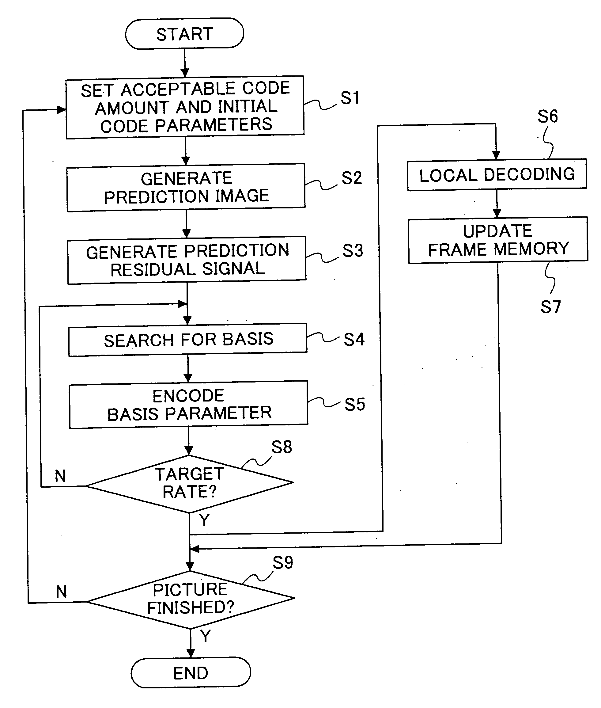
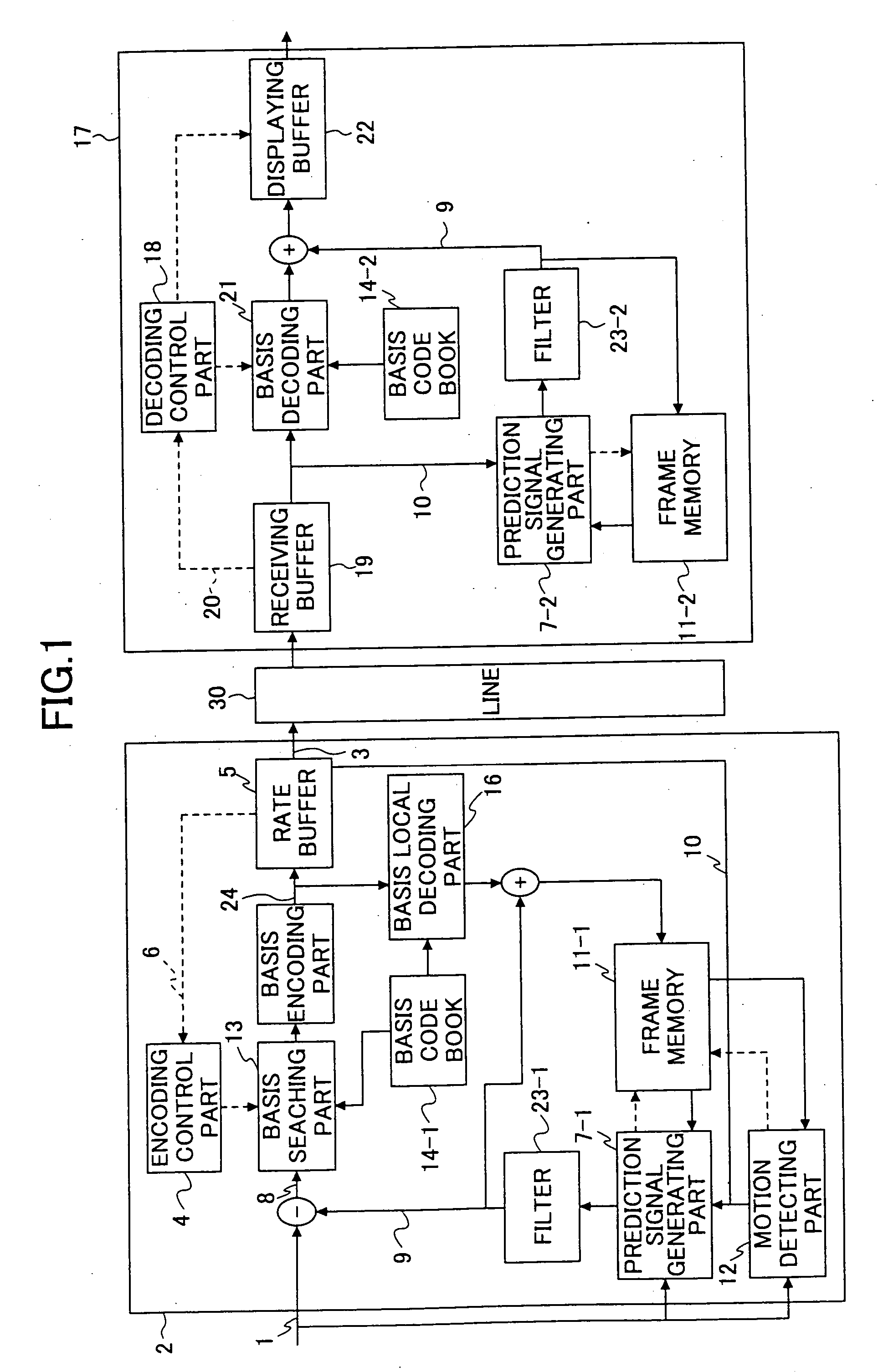
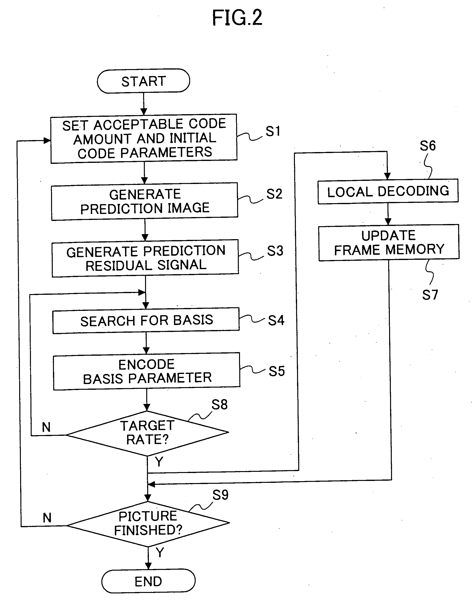
[0054] For example, an image encoder and an image decoder according to the present invention are constructed as is shown in FIG. 1. In the example, the “Matching Pursuits” (pattern matching) technique is used to perform a single layer picture encoding and decoding.

[0055] In FIG. 1, an image encoder 2 comprises an encoding control part 4, a rate buffer 5, a prediction signal generating part 7-1, a frame memory 11-1, a motion detecting part 12, a basis searching part 13, a basis code book 14-1, a basis encoding part 15, a basis local decoding part 16 and a filter 23-1. Also, an image decoder 17, which is connected with the image encoder 2 via a predetermined line 30, comprises a decoding control part 18, a receiving buffer 19, a basis decoding part 21, a displaying buffer 22, a filter 23-2, a frame memory 11-2, a prediction signal generating-part 7-2 and a basis code book 14-2.

[0056] In the following, a description will be given of an operation on the image decoder 2 (encoding proced...

second embodiment

[0088] A description will now be given of an image encoder and an image decoder according to the present invention. Especially in this embodiment, a description will be given of an example of an image encoder and an image decoder to perform a quality hierarchical encoding and a transmission by using the “Matching Pursuits”. In the image encoder and the image decoder according to the embodiment, the “Matching Pursuits” provides a basis representation of an encoding distortion signal, which is transmitted as additional information. As a result, when a line in use has a good condition, it becomes possible to transmit a high quality picture.

[0089]FIG. 8 shows a structure of the image encoder and the image decoder according to the embodiment of the present invention.

[0090] In FIG. 8, the image encoder comprises an encoding control part 111, a base-layer encoding part 102, a base-layer local decoding part 103, a base-layer frame memory 104-1, an enhance-layer encoding part 106 and a rate...

third embodiment

[0103] A description will now be given of an image encoder and an image decoder according to the present invention.

[0104] In this embodiment, a description will be given of another example of an image encoder and an image decoder to perform a quality hierarchical encoding and a transmission by using the “Matching Pursuits”. In the image encoder and the image decoder according to the embodiment, unlike the second embodiment of the present invention, an encoding distortion signal to be encoded is divided into a plurality of classes of signal patterns, and a signal pattern is classified without the use of additional information with reference to code parameters in the base layer. A control part is designed to use a code book aiming at an individual pattern. As a result, it is possible to perform the “Matching Pursuits” encoding more efficiently.

[0105]FIG. 11 shows a structure of the image encoder and the image decoder according to the embodiment of the present invention, wherein those...


PUM


Abstract

A method and an apparatus improving the coding efficiency by representing encoded data in a compact form by means of a pattern matching technique. A waveform vector similar to a partial signal waveform of an image signal in a predetermined group of waveform vectors is searched for. When a compression encoding is performed for information to identify the waveform vector searched for, similarity information, and a position in an image signal of the partial signal waveform in accordance with a predetermined encoding rule, the position in the image signal of the partial signal waveform is encoded through replacement with position information in a predetermined partial domain of the image signal. As a result; since the position in the image of the partial signal waveform that is the most similar to the waveform vector is encoded through replacement with the position information in the predetermined partial domain of the image signal, it is possible to represent the position more compactly.

Description

CROSS-REFERENCE TO RELATED APPLICATIONS [0001] This application is a Divisional of U.S. patent application Ser. No. 10 / 297,488, filed Dec. 9, 2002, which is a National Stage of International Application PCT / JP02 / 03498, filed Apr. 8, 2002, and claims priority to Japanese Patent Application No. 2001-110663, filed Apr. 9, 2001.BACKGROUND OF THE INVENTION [0002] The present invention relates to an image encoding and decoding method for encoding a source image such as a moving image and a still image and decoding the encoded image and, more particularly, to an image encoding method, an image encoder, an image decoding method and an image decoder that can encode an image and decode the encoded image with no use of DCT (discrete cosine transform) employed in standard algorithms of MPEG series and so on. [0003] Furthermore, the present invention relates to an image processing system that encodes and decodes an image in accordance with such an image encoding method and an image decoding meth...

Claims


Application Information

Patent Timeline
IPC IPC(8): G06K9/36H04N19/50G06T9/00H03M7/36H04N19/107H04N19/124H04N19/137H04N19/147H04N19/176H04N19/196H04N19/30H04N19/423H04N19/46H04N19/503H04N19/51H04N19/513H04N19/567H04N19/593H04N19/70H04N19/86H04N19/90H04N19/91H04N19/96H04N19/97
CPCG06T9/008H04N19/172H04N19/30H04N19/63H04N19/115H04N19/61H04N19/97H04N19/124H04N19/146H04N19/152H04N19/1883H04N19/64H04N19/107
Inventor SEKIGUCHI, SHUNICHIETOH, MINORUKOBAYASHI, MITSURU
Owner NTT DOCOMO INC
Features
  • R&D
  • Intellectual Property
  • Life Sciences
  • Materials
  • Tech Scout
  • Unparalleled Data Quality
  • Higher Quality Content
  • 60% Fewer Hallucinations
Learn More