Reactor having improved heat transfer

a heat exchanger and heat transfer technology, applied in the field of surface catalytic reactions and/or heat exchange, can solve the problems of unsatisfactory gap between, and achieve the effect of prolonging the useful life of the catalytic reactor or heat exchanger and being easy to manufactur

Active Publication Date: 2007-02-01
JOHNSON MATTHEY PLC
View PDF26 Cites 42 Cited by
  • Summary
  • Abstract
  • Description
  • Claims
  • Application Information

AI Technical Summary

Benefits of technology

[0018] The invention has the further object of preventing the formation of a gap between a reactor or heat exchanger and the outer tube which encases it.
[0019] The invention has the further obj

Problems solved by technology

This structure compensates for the metal creep which causes the outer tube to ex

Method used


Image

  • Reactor having improved heat transfer
  • Reactor having improved heat transfer
  • Reactor having improved heat transfer

Examples


Embodiment Construction

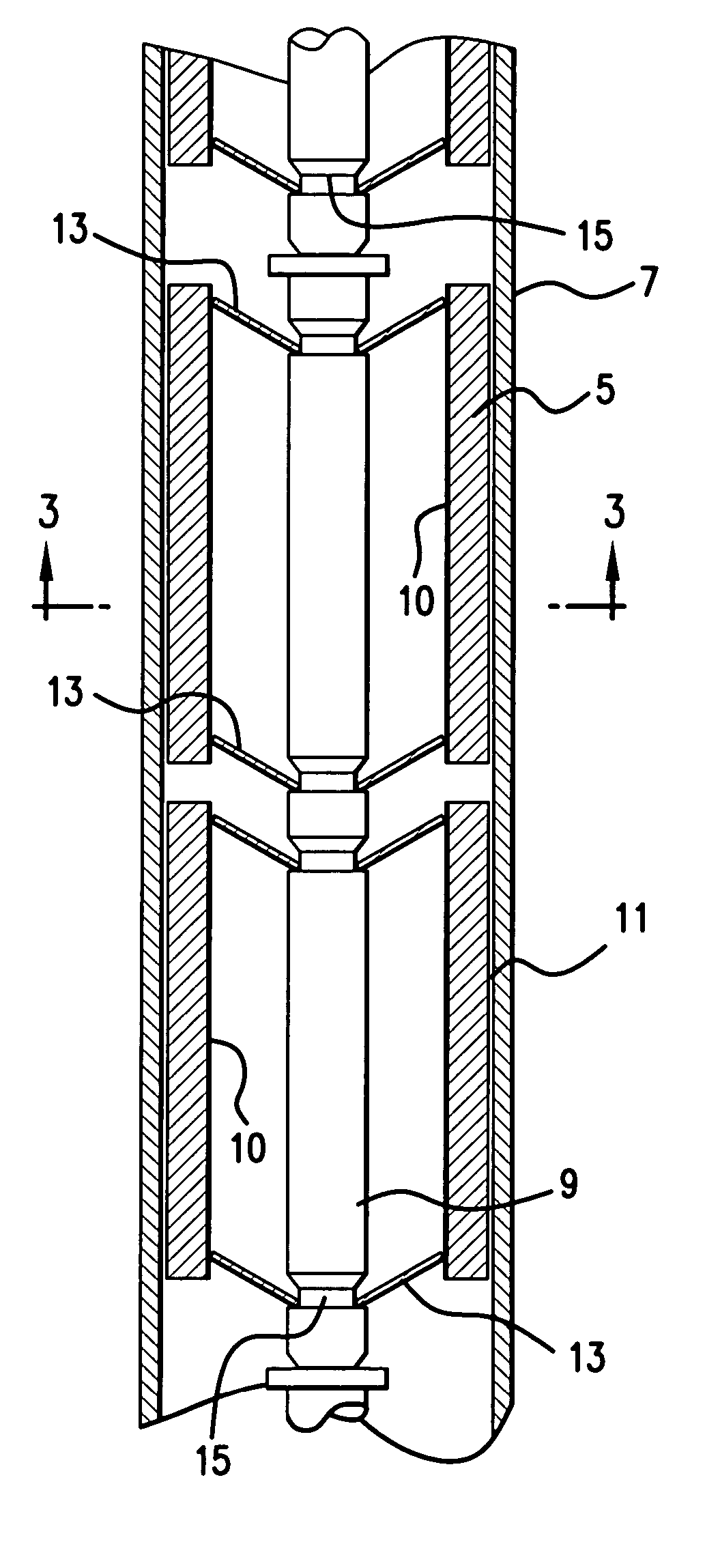
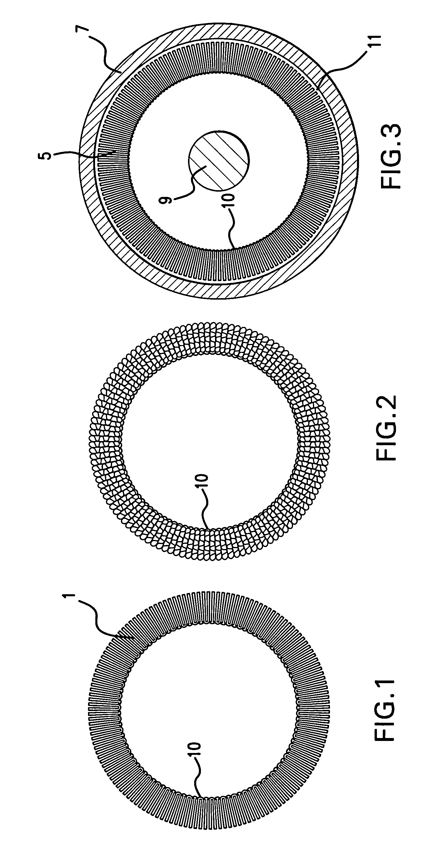
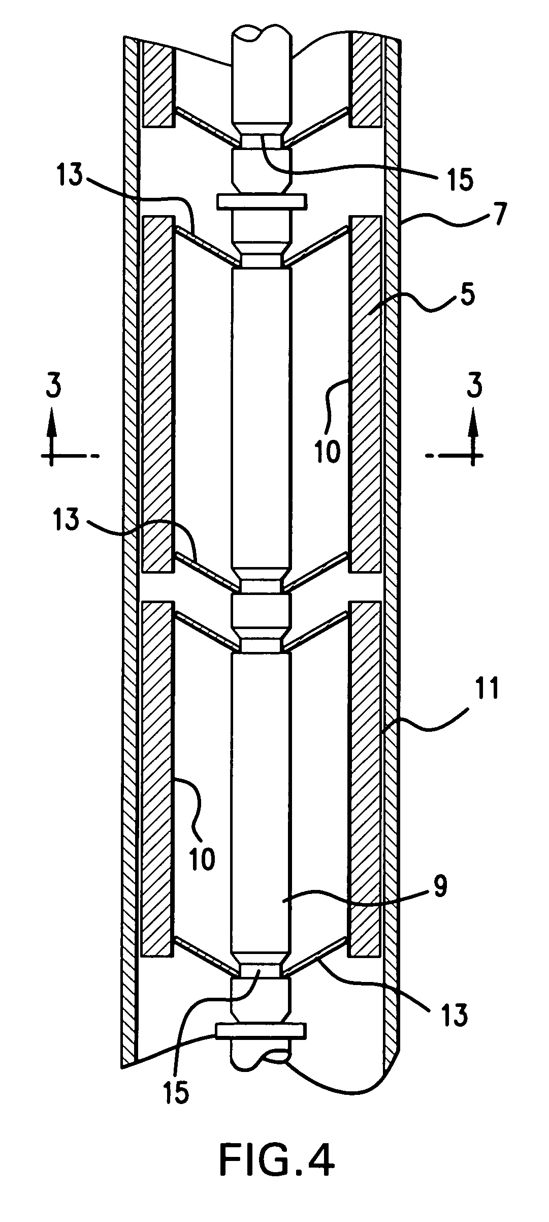
[0027] The reactor of the present invention comprises a catalyst support, preferably made of metal foil, the metal foil comprising a plurality of leaves or fins which define a relatively large surface area for catalytic combustion or heat exchange. In a preferred embodiment, the leaves are formed by folding the metal foil back and forth upon itself to define a monolith. The terms “leaves” and “fins” are used interchangeably in this specification. If the monolith is used for catalytic reactions, its surfaces are coated with a suitable catalyst.

[0028] In one aspect of the invention, the reactor has the form of an annulus. That is, the reactor comprises a strip of metal foil that has been folded back and forth upon itself many times, but wherein the folded strip defines a generally annular cross-section, as viewed in the direction of the flow of gas through the reactor. The reactor is inserted within a cylindrical outer tube, the other side of the reactor being bounded by an expandabl...


PUM

PropertyMeasurementUnit
Metallic bondaaaaaaaaaa

Abstract

A catalytic reactor or heat exchanger includes a monolith defining a plurality of leaves, the monolith having a generally annular cross-section. The monolith is disposed within a generally cylindrical outer tube, and around a corrugated inner tube. The reactor includes a device for urging the monolith radially outward, so as to maintain contact between the monolith and the outer tube. Such device may include a coned washer, or it may be defined by a folded flap that is integral with the inner tube. In either case, the reactor compensates for metal creep, and virtually insures continued contact between the monolith and the outer tube.

Description

BACKGROUND OF THE INVENTION [0001] This invention relates to the field of surface catalytic reactions and / or heat exchange. The present invention provides a reactor which fits within a cylindrical outer tube, and which effectively transfers heat from the exterior of the outer tube to the reactor, or from the reactor to the outer tube. [0002] The reactor of the present invention achieves the same objectives as those of the catalyst supports described in copending U.S. patent application Ser. No. 11 / 132,691, filed May 19, 2005, Ser. No. 10 / 896,302, filed Jul. 21, 2004, and Ser. No. 11 / 105,973, filed Apr. 14, 2005. The disclosures of the above-mentioned applications are incorporated by reference herein. [0003] One of the objectives of the reactors described in the above-cited applications is to avoid the problems associated with the use of ceramic materials in the manufacture and operation of catalytic reactors. Packed bed ceramic catalysts have the disadvantage that they have low ther...

Claims


Application Information

Patent Timeline
IPC IPC(8): B01J8/02
CPCB01J12/007Y10T428/24744B01J19/2485B01J19/32B01J19/325B01J2219/00087B01J2219/32279B01J2219/32408B01J2219/32466B01J2219/32475B01J2219/3281F28F1/40F28F13/06Y10T428/1234Y10T428/24149B01J19/2415
Inventor WHITTENBERGER, WILLIAM A.BECKER, DAVID A.CHATTOPADHYAY, SUDIPTASUFFECOOL, L. AMANDA
Owner JOHNSON MATTHEY PLC
Why Eureka
Try Eureka