Pressure limiting forceps

Inactive Publication Date: 2007-02-01
LASNER JEFFREY
View PDF4 Cites 25 Cited by
  • Summary
  • Abstract
  • Description
  • Claims
  • Application Information

AI Technical Summary

Benefits of technology

[0006] Furthermore, in the preferred embodiment of the invention, additional stress relief is obtained by means of the flexible interlocking sleeves at the distal end of the forceps. It should

Problems solved by technology

In the surgical field, it is known that a problem exists in the handling of tissues and grafts with conventional forceps.
Too little pressure will result in slippage, and too much force applied to the forceps could result in tearing, puncturing, abrasion or scoring which is the primary reason for tissue breakdo

Method used


Image

  • Pressure limiting forceps
  • Pressure limiting forceps
  • Pressure limiting forceps

Examples


Example

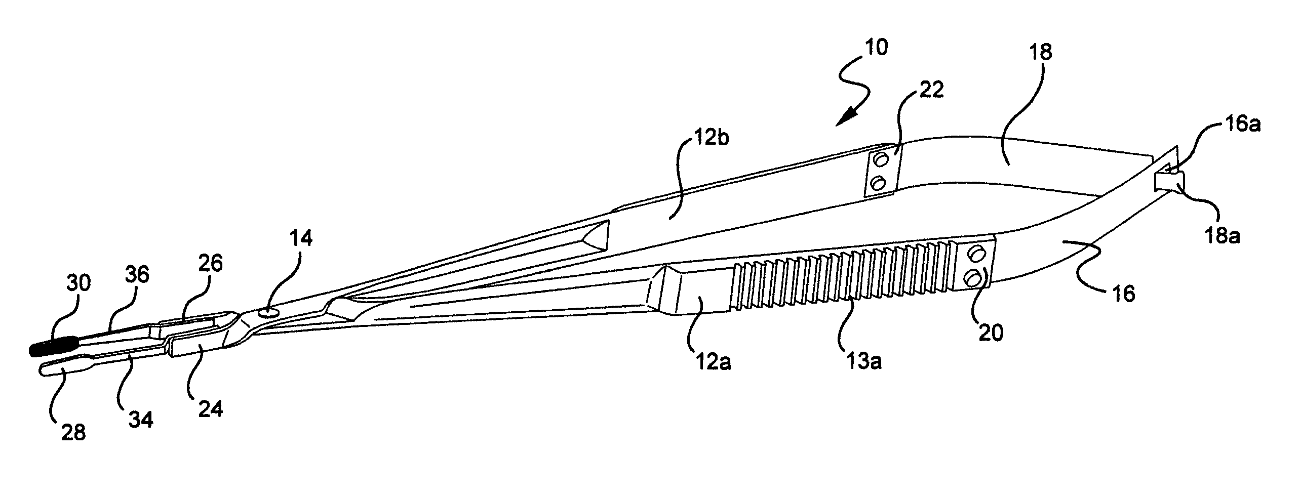
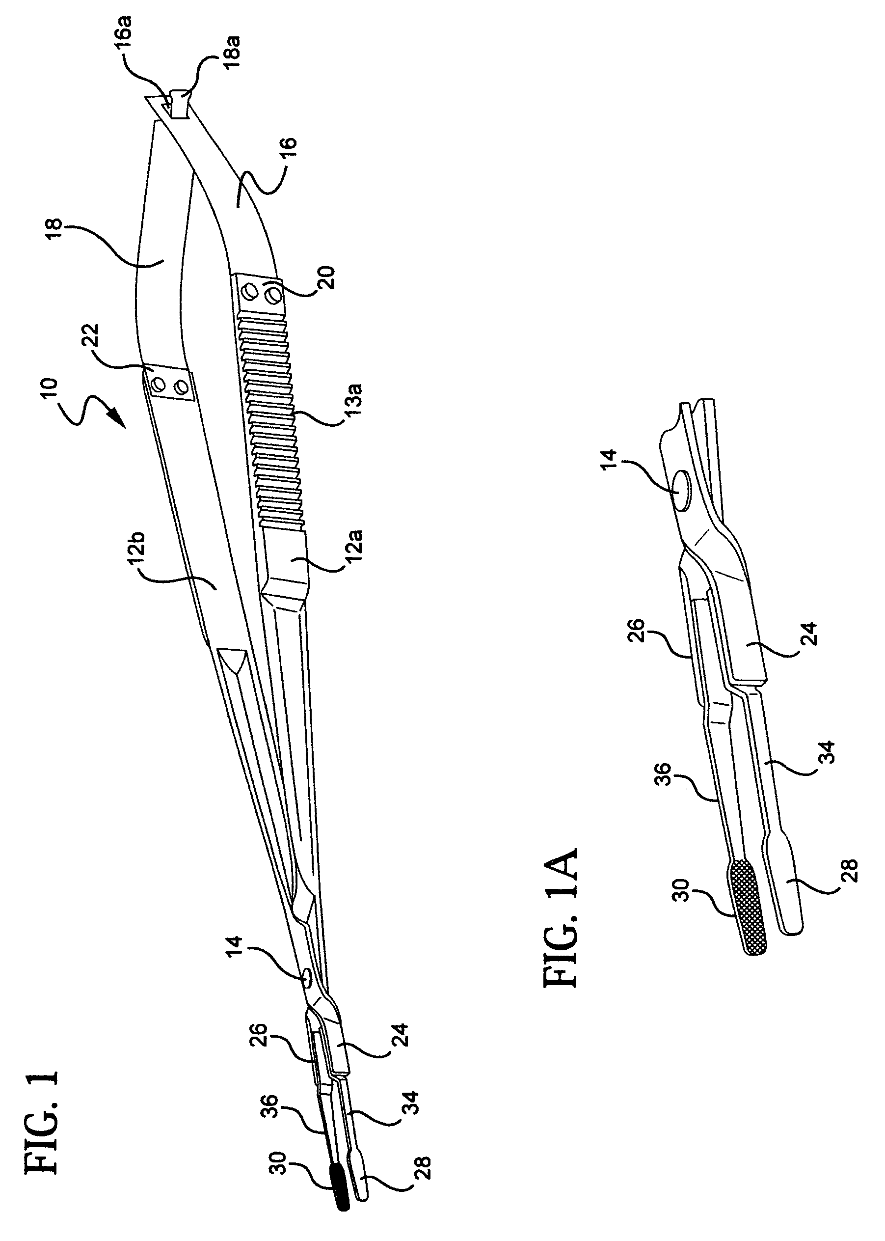
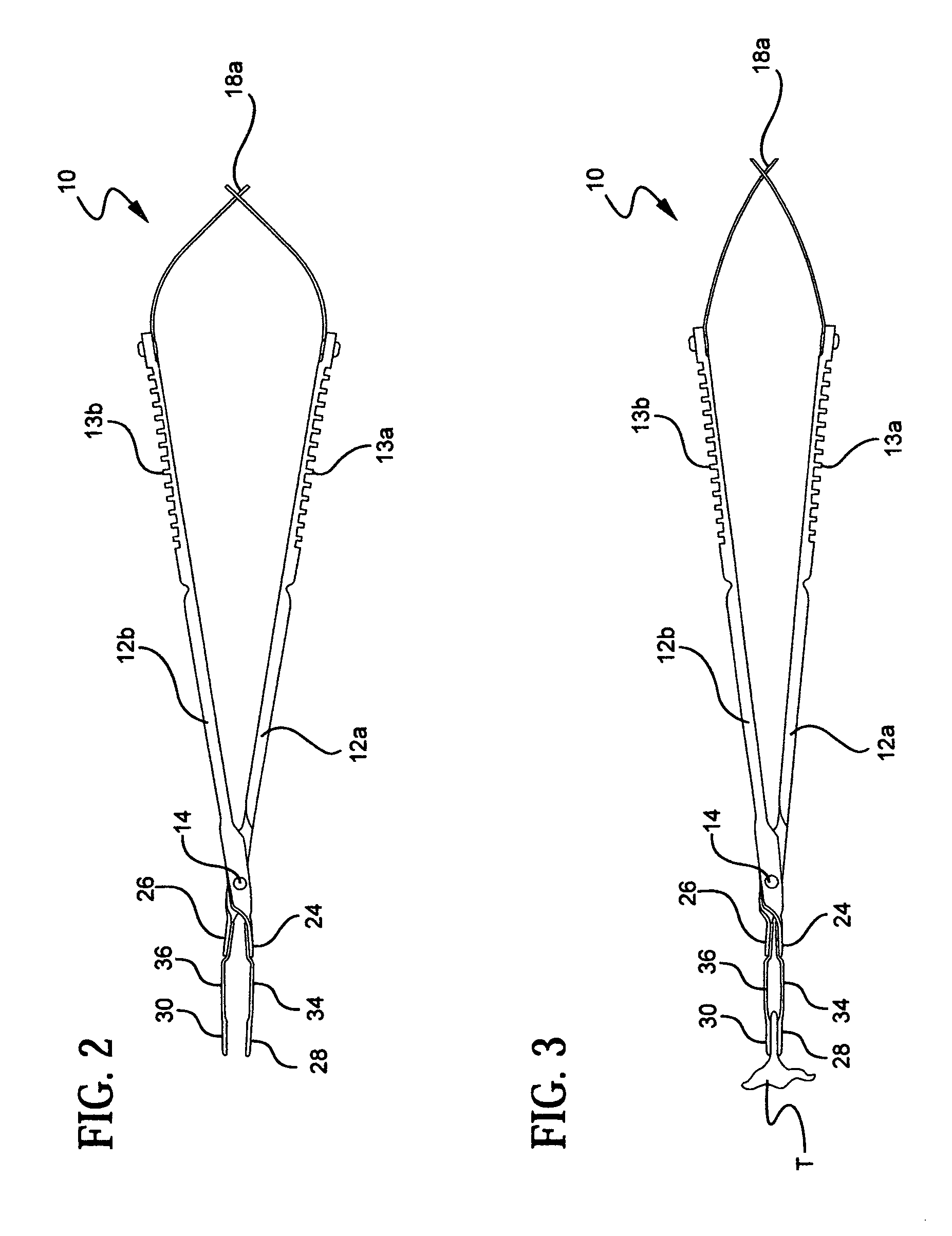
[0014] Forceps are presently used by health professionals, such as surgeons, in connection with procedures involving tissue manipulation. In order to ensure the proper amount of pressure is applied and controlled the present invention, as shown in FIGS. 1-3 of the drawings, has been devised in which the pressure limiting forceps is shown generally by the numeral 10. The main body of the forceps includes a handle that is provided with two parts 12a and 12b respectively which are pivotally connected at the forward end of the forceps by means of pivot 14. The handles 12a and 12b are provided with slip resistant grasping surfaces 13a and 13b. The distal end of the forceps has flexible interlocking bands 16 and 18 each being attached at to the handles 12a and 12b by securing means 20 and 22. The other ends of the flexible bands 16 and 18 are male-female connected by means of projection 18a of band 18 free sliding in opening 16a of the band 16.

[0015] As seen in FIG. 1A, the forward end o...


PUM


Abstract

Forceps of the tips that are commonly used in surgical procedures having pressure limiting means that is effective after the tissue or material is firmly grasped by the platforms or tips, thus causing pressure being applied and competent damage to the tissue or material being handled by the forceps.

Description

PRIORITY CLAIM [0001] This invention was first filed as a U.S. provisional Application No. 60 / 699,574 on Jul. 15, 2005. The filing date and priority of this first filing is expressly claimed pursuant to 35 U.S.C. § 119 (e).FIELD OF THE INVENTION [0002] This invention relates generally to forceps used in a surgical procedure relating to tissue and grafts having a construction which limits or reduces the pressure on the surgeon's hand while doing said procedure but maintaining a secure grasp with minimal pressure. BACKGROUND OF THE INVENTION [0003] In the surgical field, it is known that a problem exists in the handling of tissues and grafts with conventional forceps. When using currently available forceps the closing force is transmitted directly and proportionally to the tips of the forceps. As a consequence the surgeon needs to be aware of the pressure exerted on the tissue during manipulation. Too little pressure will result in slippage, and too much force applied to the forceps c...

Claims


Application Information

Patent Timeline
IPC IPC(8): A61B17/08
CPCA61B17/30A61B2019/302A61B19/30A61B2090/032A61B90/03
Inventor LASNER, JEFFREY
Owner LASNER JEFFREY
Why Eureka
Try Eureka