Potential separation for fill level radar

a radar and potential separation technology, applied in the field of fill level measurement, can solve problems such as feed material ignition or damage, and achieve the effect of saving spa

a radar and potential separation technology, applied in the field of fill level measurement, can solve problems such as feed material ignition or damage, and achieve the effect of saving spa

US20070028829A1Active Publication Date: 2007-02-08VEGA GRIESHABER GMBH & CO

Image

  • Potential separation for fill level radar
  • Potential separation for fill level radar
  • Potential separation for fill level radar

Examples


Embodiment Construction

[0047] In the following description of the figures the same reference characters are used for identical or similar elements.

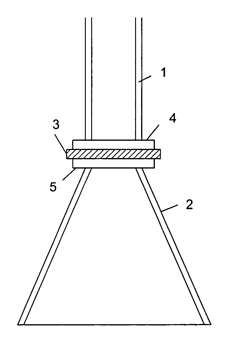
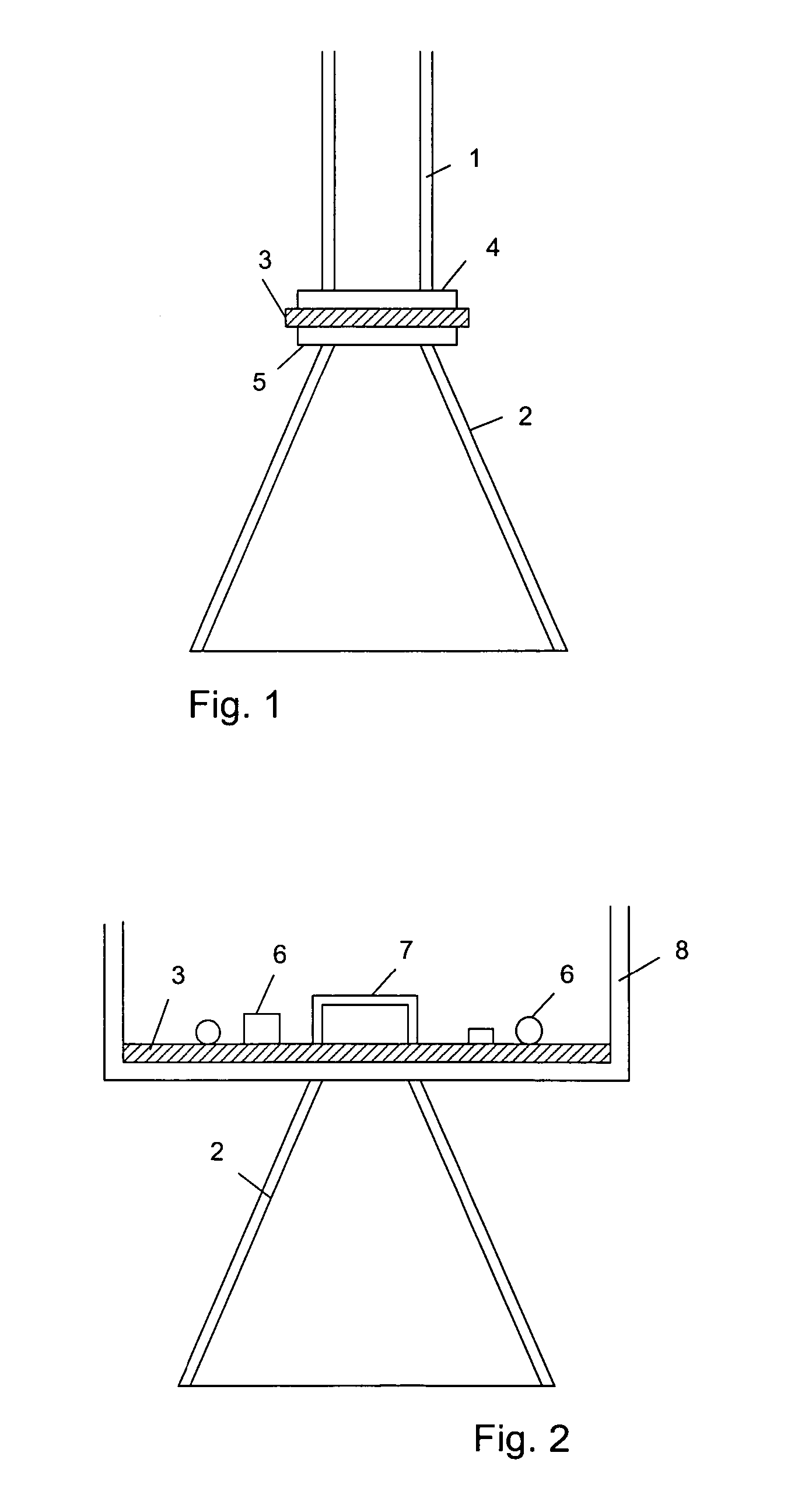
[0048]FIG. 1 shows part of a fill level radar with potential separation according to an exemplary embodiment of the present invention. As shown in FIG. 1, the arrangement comprises a hollow conductor 1 (i.e. a waveguide) that is provided for conducting electromagnetic waves, an aerial 2 for transmitting and / or receiving electromagnetic waves, and a separation element 3 for insulating the aerial 2 from the hollow conductor 1. As is shown in FIG. 1, the separation element 3 is arranged directly at the aerial 2. To this effect the aerial 2 comprises a connecting element 5. The separation element 3 may, for example, be vapour deposited or deposited in some other way onto the connecting element 5. Of course, it may be also possible for the separation element 3 to be glued or clipped onto the connecting element, or to be attached in some other way.

[0049] The hollow...


PUM


Abstract

For safety reasons the potential of an electrical supply line of a radar sensor may be separated from the potential of the fill level container. A fill level radar with potential separation includes a separation element for insulating the aerial from a feed device. The separation element is arranged directly at the aerial, or forms part of the aerial. In this way insulation of the aerial from the exterior of the container is provided.

Description

REFERENCE TO RELATED APPLICATIONS [0001] This application claims the benefit of the filing date of United States Provisional Patent Application No. 60 / 705,597 filed Aug. 4, 2005, and of German Patent Application 10 2005 036 715.1 filed Aug. 4, 2005, the disclosures of which are hereby incorporated herein by reference.FIELD OF THE INVENTION [0002] The present invention relates to fill level measuring. In particular, the present invention relates to a fill level radar with potential separation for determining the fill level in a tank, to an aerial, and to method for determining the fill level in a tank. TECHNOLOGICAL BACKGROUND [0003] For considerations relating to measuring technology and for safety reasons the potential of the electrical supply line of a radar sensor may be separated from the potential of the, often metallic, fill level container. This may for example result in a reduction in noise effects during measuring, and to a reduction in the susceptibility to interference of...

Claims


Application Information

Patent Timeline
08 Feb 2007
Publication
US20070028829A1
IPC
B63B17/00
CPC
G01F23/284
Inventors
GRIESSBAUM, KARL; FEHRENBACH, JOSEF