

Heat sink
a heat sink and heat conductor technology, applied in the field of heat sinks, can solve the problems of reducing the working efficiency of integrated circuits, affecting the efficiency of heat sinks, so as to improve heat conductivity efficiency, and cool the integrated circuit effectively
- Summary
- Abstract
- Description
- Claims
- Application Information
AI Technical Summary
Benefits of technology
Problems solved by technology
Method used
Image

Examples
Embodiment Construction
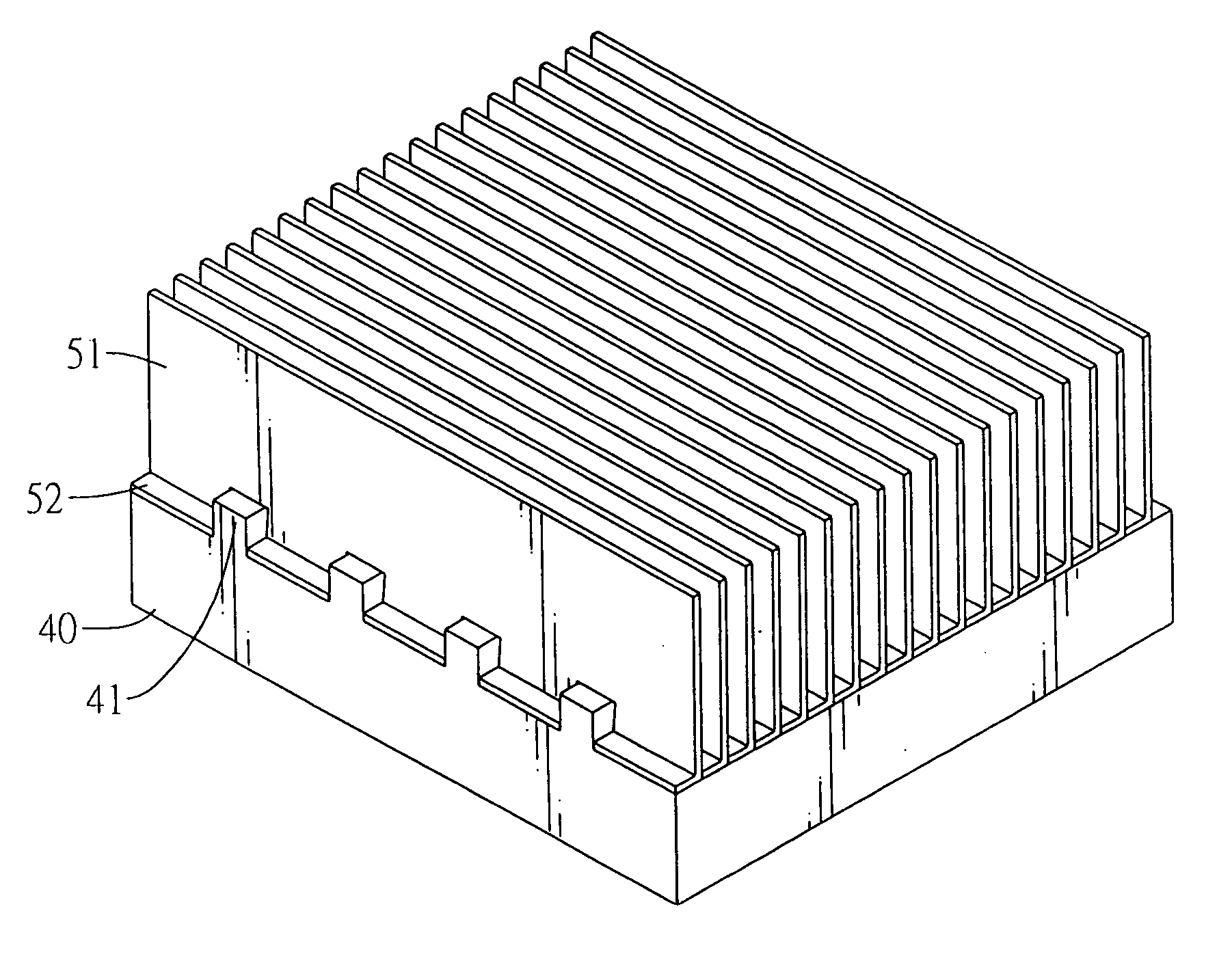
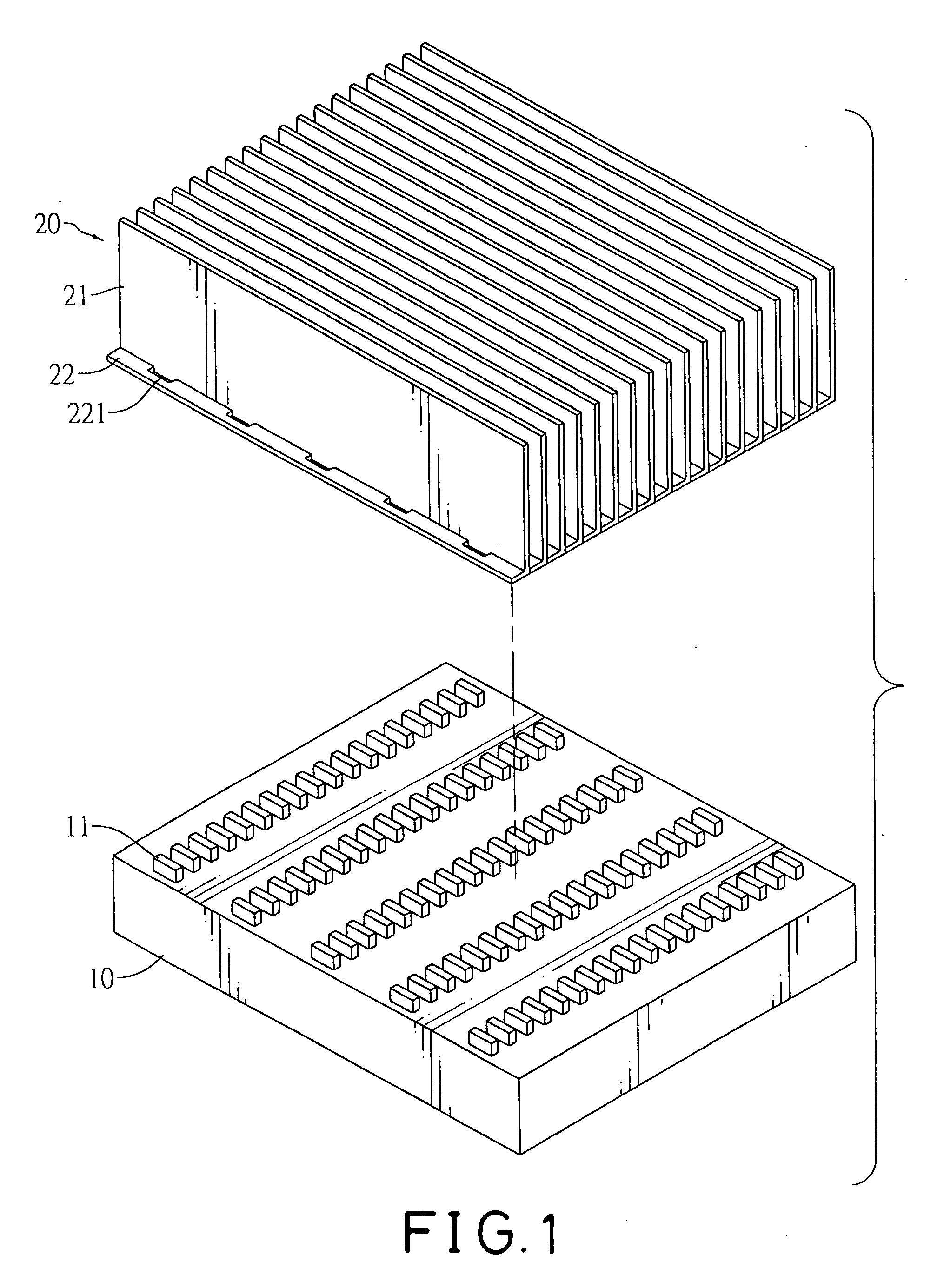
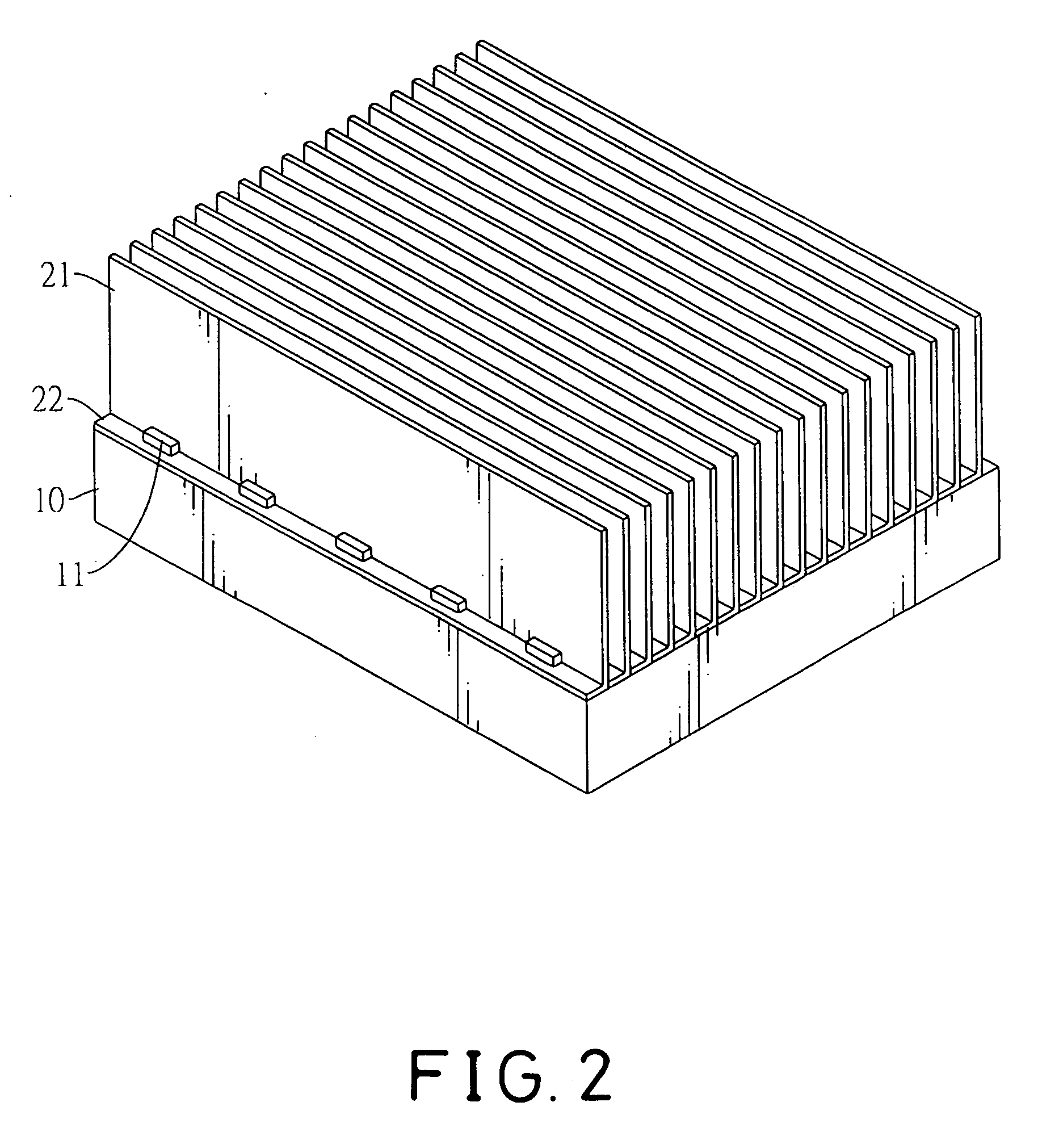
[0025] With reference to FIGS. 1, 6 and 10, a heat sink in accordance with the present invention comprises a base (10, 40, 60) and multiple fins (20, 50, 70).
[0026] The base (10, 40, 60) may have multiple protrusions (11), multiple ribs (41) or multiple inclined slots (61). The protrusions (11) are formed separately on the base (10) and may be parallel to each other, and each protrusion (11) has an enlarged distal end. The ribs (41) are formed separately on the base (40) and may be parallel to each other, and each rib (41) has an enlarged distal end. The inclined slots (61) are formed separately in the base (60) and may be parallel to each other and at an inclined angle.
[0027] The fins (20, 50, 70) are attached to the base (10, 40, 60), and each fin (20, 50, 70) has a radiating surface (21, 51, 71) and a conducting surface (22, 52, 72).
[0028] Each radiating surface (21, 51, 71) has a distal end and a proximal end and may have multiple notches (511). The notches (511) are formed s...
PUM
 Abstract
Description
Claims
Application Information