
Portable observation tower and system for operation

a technology for observation towers and systems, applied in the field of observation towers, can solve the problems of cumbersome movement of such a tower, towers that can be placed in less than ideal locations, and typical towers that require a large amount of time to assemble and erect, so as to reduce the overall length and width of legs and reduce the angle of front legs

Inactive Publication Date: 2007-02-08
KIRBY JERRY
View PDF22 Cites 7 Cited by
  • Summary
  • Abstract
  • Description
  • Claims
  • Application Information

AI Technical Summary

Benefits of technology

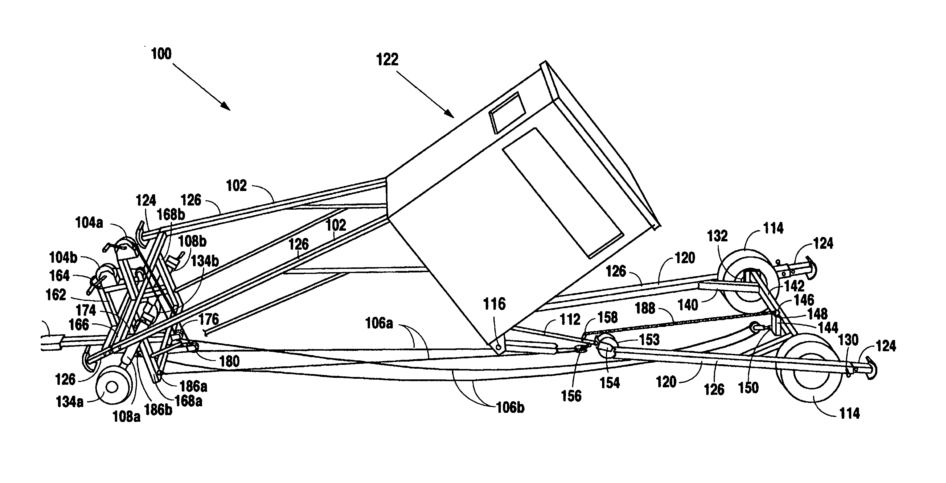
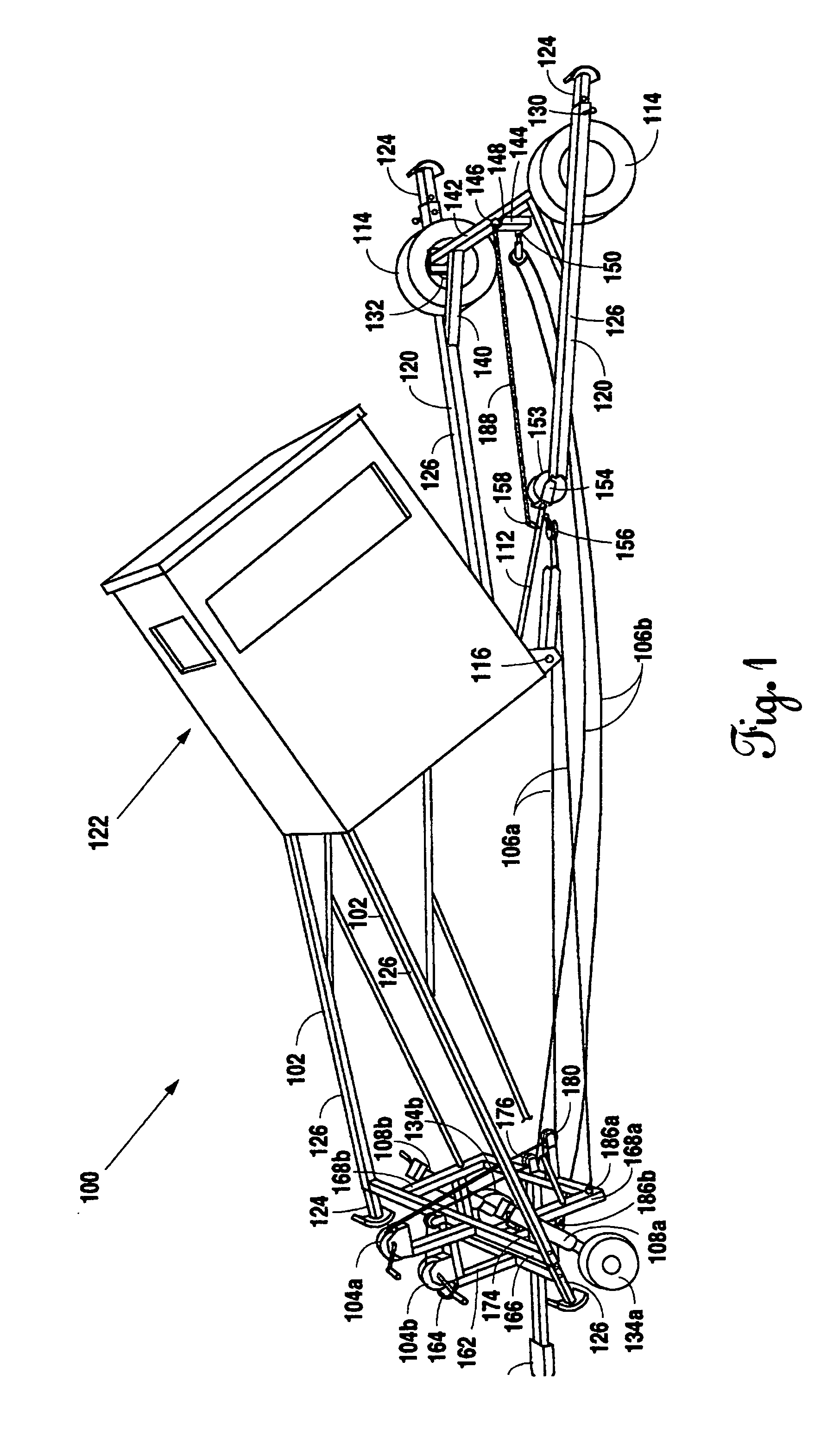
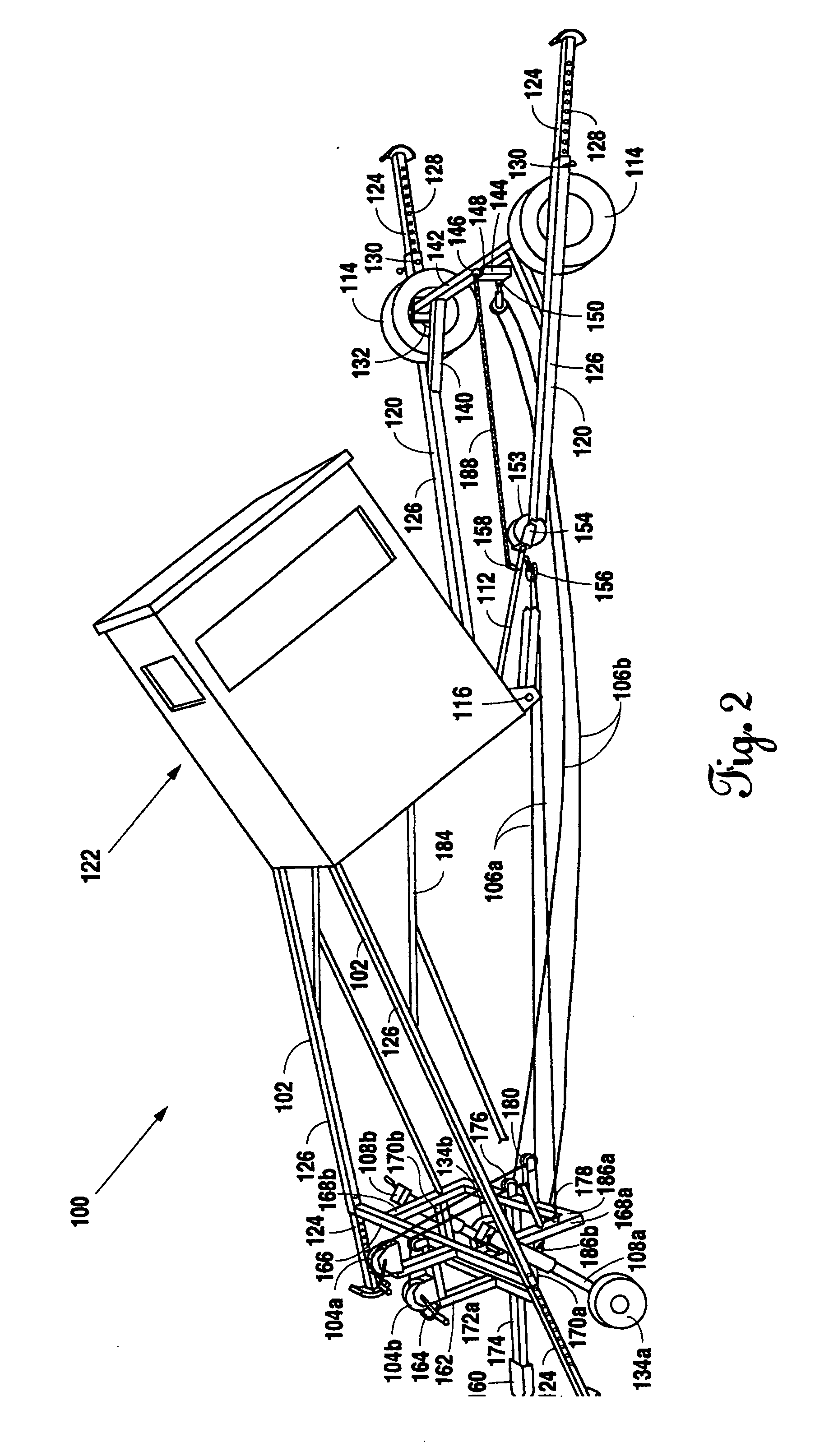
[0006] The preferred embodiment of the present invention includes a portable observation tower and a system of raising and lowering the portable observation tower. The tower has a tower box. There are two front legs attached in a fixed position to the tower box. There are two back legs attached on a hinge system to the tower box which allows the back legs to swivel in relation to the tower box. Each leg of the tower has two sections. A first section of the legs is telescoped inside a second section to reduce the overall length and width of the legs and the tower as a whole. Once the desired length for the legs is acquired, a locking pin will fix the legs into the desired position. In raising the tower, the front legs are pulled toward the back legs with a winch system that is mounted on a front trailer hitch system on the front legs. By pulling in this manner, the tower will raise to a vertical upright position.
[0007] More specifically, the angle between the front legs and the back legs is almost 180 degrees so rolling landing gear is used to be lowered and drawn by the a winch to a frontmost position. The rolling landing gear is installed adjacent the hinge system of the back legs. The rolling landing gear is attached by way of a winch line to a winch. By lowering the rolling landing gear and pulling it forward with the winch line to a locking position (slanted toward the front legs) the rolling landing gear raises the mid section of the tower box and thereby reduces the angle of the front legs to the back legs. Once this is completed a winch line is attached to an axle of the back legs to draw the back legs to the front legs by way of a winch. By drawing the front and back legs together the tower is elevated to its full upright position.
[0008] There are trailer wheels mounted on the back legs which aid in forward movement of the back legs toward the front legs. There is also a screw type trailer jack mounted on the front trailer hitch system which has a rolling wheel that aids in the rearward movement of the front legs toward the back legs in the raising process. The lowering process occurs in reverse order of the raising process. The wheels and winch are also used in reverse order for the lowering process.

Problems solved by technology

The typical observation tower is designed in a rigid manner requiring that the user take special efforts to find the ideal location for placement because moving such a tower can be cumbersome.
In addition, the typical tower requires a large amount of time to assemble and erect.
Unfortunately most users are in need of observation towers that can be placed in less than ideal locations within a small time window.

Method used


Image

  • Portable observation tower and system for operation
  • Portable observation tower and system for operation
  • Portable observation tower and system for operation

Examples


Embodiment Construction

[0016] In FIG. 1 a perspective view of the preferred embodiment of the present invention in its trailer configuration is shown. The portable observation tower 100 is provided with a tower box 122 having two front legs 102 and two back legs 120. The two front legs 102 are attached at one end in a fixed position to the tower box 122. The two back legs 120 are attached at one end on a hinge system 116 to the tower box 122. The hinge system 116 allows the back legs 120 to swivel in relation to the tower box 122. Back leg trailer wheels 114 are provided to aid movement of front legs 102 in relation to back legs 120. Back leg trailer wheels 114 connect to wheel bars 142. Wheel bars 142 are attached to axle 132. Centrally positioned along axle 132 is winch line post 144. Winch line post 144 lies perpendicular to axle 132 and has a first eye 146 at its upper end 148 and a second eye 150 positioned along the side of the base of the winch line post 144. Second winch line 106b attaches to seco...


PUM


Abstract

A portable observation tower and system of raising and lowering the tower is disclosed. The tower has a tower box with two fixed sectioned front legs and two hinged sectioned back legs. To raise the tower front legs are pulled toward back legs with a winch system mounted on a trailer hitch system. Rolling landing gear is lowered and drawn by winch to a front most locking position. This raises the mid section of tower box reducing the angle of front legs to back legs. Once complete the winch line can be attached to an axle of back legs to draw back legs to front legs. This process elevates tower to its full upright position. Wheels are provided on back legs and on trailer hitch system for movement of the tower. The lowering process occurs in reverse order of the raising process.

Description

[0001] This application claims priority to U.S. Provisional Application Ser. No. 60 / 705,352 filed Aug. 4, 2005 and U.S. Provisional Application Ser. No. 60 / 740,497 filed Nov. 29, 2005.BACKGROUND OF THE INVENTION [0002] 1. Field of the Invention [0003] Applicant's invention relates to an observation tower. More specifically, the present invention relates to an observation tower that can be easily moved from once place to another and erected on site with minimal effort. [0004] 2. Background Information [0005] Observation towers are useful to users because such towers permit a wide view of their surroundings. The typical observation tower is designed in a rigid manner requiring that the user take special efforts to find the ideal location for placement because moving such a tower can be cumbersome. In addition, the typical tower requires a large amount of time to assemble and erect. Unfortunately most users are in need of observation towers that can be placed in less than ideal locatio...

Claims


Application Information

Patent Timeline
Patent Type & Authority Applications(United States)
IPC IPC(8): E04C1/00
CPCA01M31/02
Inventor KIRBY, JERRY
Owner KIRBY JERRY
Learn More