
Method for coding RFID tags in printer label applications

a technology for printer labels and labels, applied in the field of identification systems, can solve the problems of difficult simultaneous printing and programming of rfid labels from a single location or device, difficult to separate or individually ascertain signals, and difficult to continuously send signals combined with backscattered response signals, etc., and achieve the effect of increasing the quantity and quality of information placed on labels

Inactive Publication Date: 2007-02-08
ENSYC TECH
View PDF9 Cites 12 Cited by
  • Summary
  • Abstract
  • Description
  • Claims
  • Application Information

AI Technical Summary

Benefits of technology

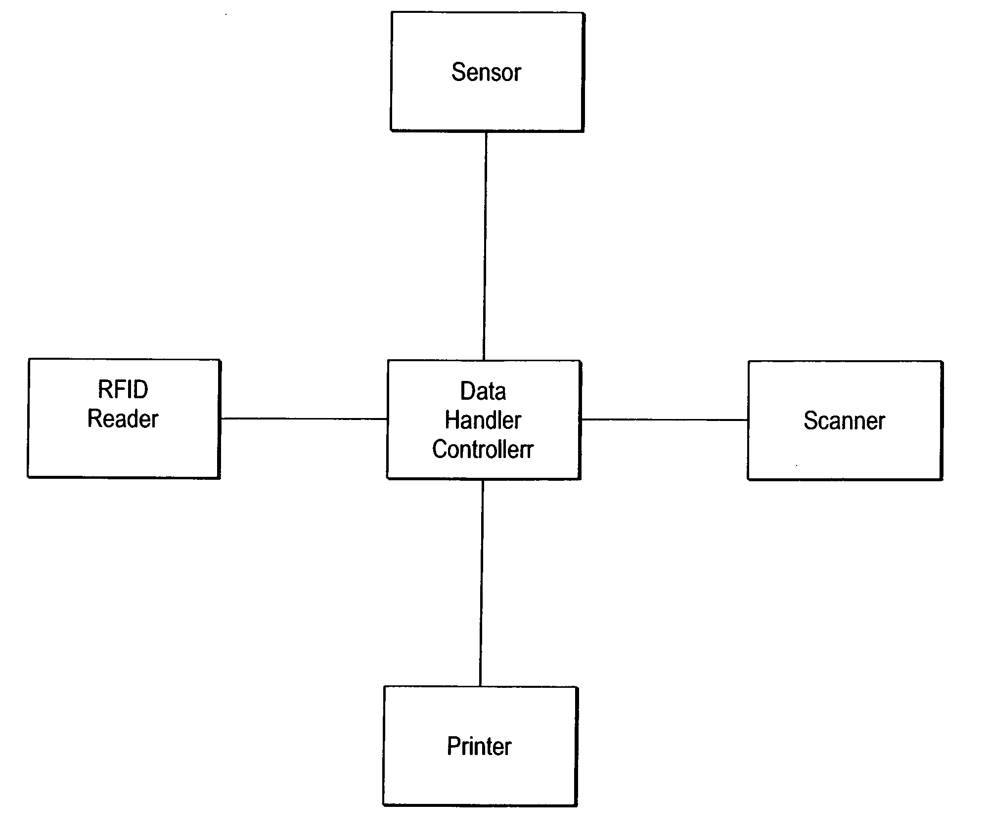
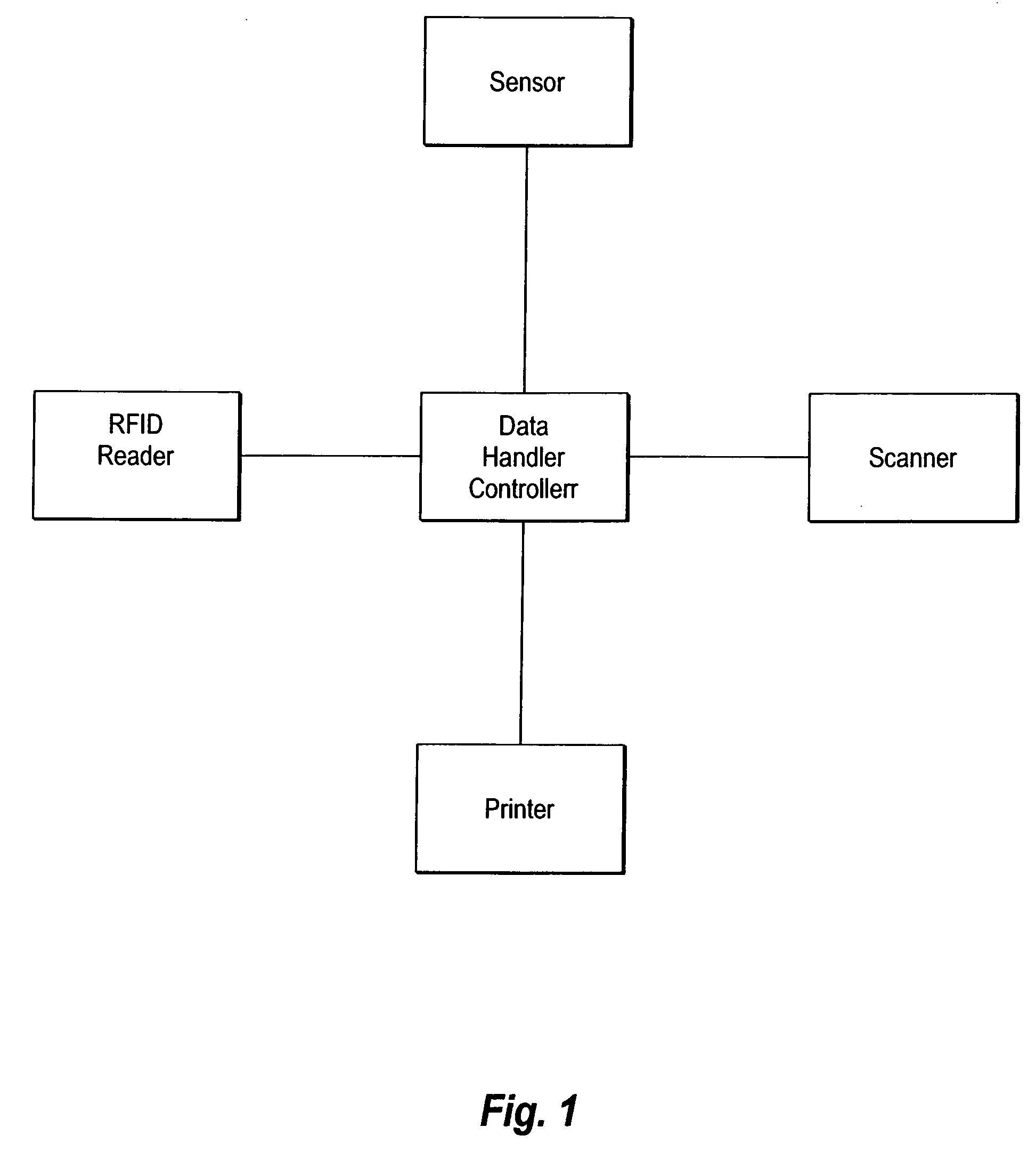
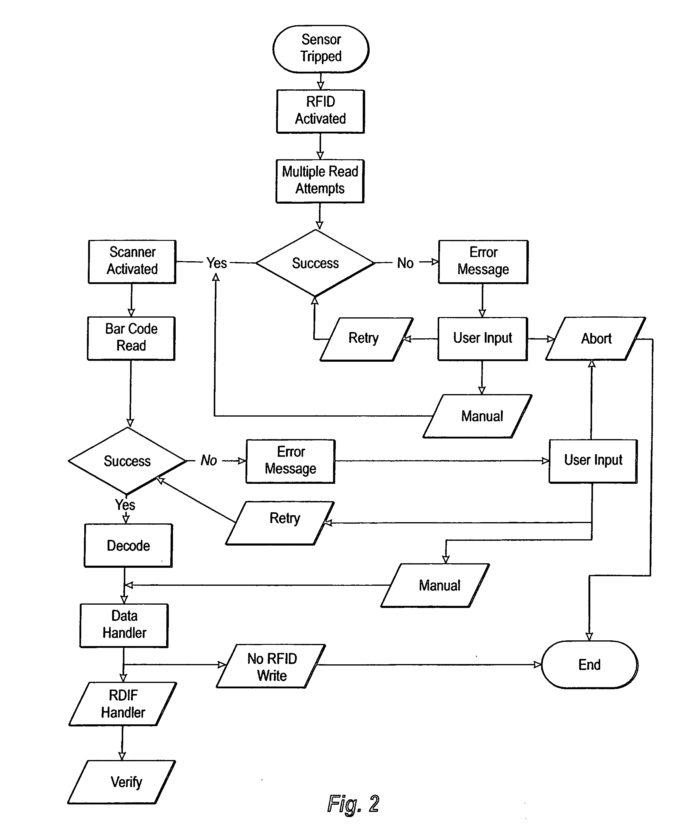
[0017] When the label passes under the sensor on the RFID reader the RFID mechanism is activated and the reader makes multiple read attempts to attempt to determine the identity of the RFID tag within the label. If the label is successfully read, then the scanner is activated and the bar code on the label is read. If the tag and the bar code and the tag are both successfully read, the data handler signals the RFID reader to write information to the tag. This information is then verified. If the tag passes through all of these steps successfully, then the tag may be utilized and placed upon a particular item. If the tag fails to pass any of these steps after various attempts to troubleshoot and rectify the problem the tag is not written and is not suitable for use. This invention provides a significant advantage over the prior art in that this device allows for the quantity and quality of information which is placed upon a tag to be significantly increased and significant amounts of information regarding an item to be placed upon a tag and for this tag to be created in a single location.

Problems solved by technology

In some circumstances, this constant sending of a signal combined with the backscattered response signals can be problematic particularly in applications where the reader is in close association with a plurality of tags or when the reader and the tags are in close contact with one another.
This results in signals which are difficult to separate or individually ascertain.
This weakness in the present system has made the simultaneous printing and programming of RFID labels from a single location or device very difficult.
Where such systems have been implemented, the equipment utilized to achieve these results has been too expensive to allow for widespread use of this technology or the use of this technology in conjunction with the many items in common commerce.

Method used


Image

  • Method for coding RFID tags in printer label applications
  • Method for coding RFID tags in printer label applications
  • Method for coding RFID tags in printer label applications

Examples


Embodiment Construction

[0022] While the invention is susceptible of various modifications and alternative constructions, certain illustrated embodiments thereof have been shown in the drawings and will be described below in detail. It should be understood, however, that there is no intention to limit the invention to the specific form disclosed, but, on the contrary, the invention is to cover all modifications, alternative constructions, and equivalents falling within the spirit and scope of the invention as defined in the claims.

[0023] While the method of the present invention is described as functioning within the Applicant's particular system described below as well as in a concurrently filed pending United States Patent Application entitled LOW COST CLOSE RANGE RFID SYSTEM FOR PRINTER LABEL APPLICATIONS and filed by the same inventor, it is to be distinctly understood that the invention is not limited to use within this particular system but may also be utilized in a variety of other physical configu...


PUM


Abstract

A method for reading and encoding RFID tags in a label printer configuration. A low cost close range RFID Reader which is operatively connected to a control device which contains a transmitter and is configured to function as a homodyne receiver. The device can be constructed from low cost parts and can function in close ranges to other tags. The method of the present invention provides the activation of reading and writing hardware to read and write information upon a tag and a label.

Description

BACKGROUND OF THE INVENTION [0001] 1. Field of the Invention [0002] The present invention generally relates to identification systems and more particularly to a method for preparing and coding RFID tags at close range, such as in a printer label application. [0003] 2. Background Information [0004] Radio Frequency Identification Systems (RFIDs) are used in a variety of industries to identify, track, and provide various other types of information related to the items upon which the tag is placed. These devices are useful in identifying and determining the various features of the products upon which these labels are placed. In order to coordinate and streamline the functionality of these labels as well as the readers which are used in conjunction with these tags, a variety of generally accepted standards and protocols have been accepted and are generally used. [0005] A typical RFID system is usually made up of at least one transmitting and receiving device commonly called a reader and ...

Claims


Application Information

Patent Timeline
IPC IPC(8): G06K7/00G06F17/00
CPCG06K1/18G06K17/0025G06K17/00G06K5/00
Inventor JESSUP, STEVEN
Owner ENSYC TECH
Learn More