Optical system for processing image using point spread function and image processing method thereof

a technology of optical system and image processing, which is applied in the field of fixed focal length optical system, can solve the problems of large volume, increased weight of optical apparatus to which optical system having auto-focusing function is applied, and inability to properly perform focusing function, etc., and achieves the effects of small psf, fast image processing speed and excellent imag

Inactive Publication Date: 2007-02-08
SAMSUNG ELECTRO MECHANICS CO LTD
View PDF18 Cites 8 Cited by
  • Summary
  • Abstract
  • Description
  • Claims
  • Application Information

AI Technical Summary

Benefits of technology

[0015] An object of the present invention is to provide an optical system and an image processing method that process an image using a PSF, capable of realizing an excellent image over a wide range of object distances including a close-up shot distance and a long distance without using a driving device.
[0016] Another object of the present invention is to provide an optical system and an image processing method that process an image using a PSF and has a small PSF and a fast image processing speed.

Problems solved by technology

Generally, an optical system of a fixed focal length cannot properly perform a focusing function because a point spread function is seriously deteriorated as a camera approaches an object.
Particularly, when a close-up shot is performed on an object distant away at about 10 cm, an image is very seriously deteriorated.
However, such an optical system requires transfer of a lens or an image sensor in order to perform the auto-focusing function, and thus a driving device for the lens or the image sensor is required.
Therefore, an optical apparatus to which an optical system having an auto-focusing function is applied has an increased weight and a large volume.
That is, according to the conventional optical system, an image quality is seriously reduced and a recovered image quality is poor.

Method used


Image

  • Optical system for processing image using point spread function and image processing method thereof
  • Optical system for processing image using point spread function and image processing method thereof
  • Optical system for processing image using point spread function and image processing method thereof

Examples


Embodiment Construction

[0044] Reference will now be made in detail to the preferred embodiments of the present invention, examples of which are illustrated in the accompanying drawings.

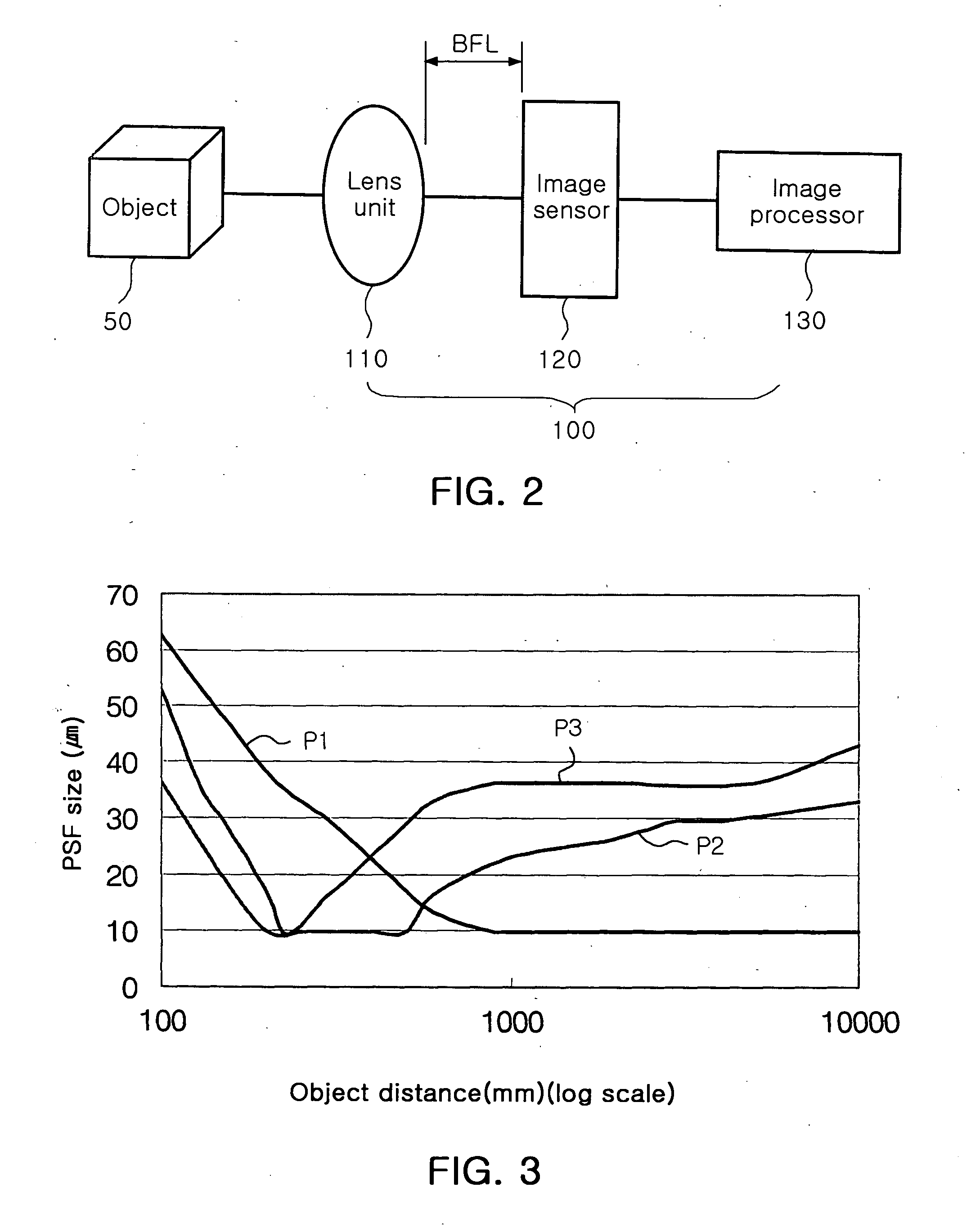
[0045]FIG. 2 is a view of an optical system for processing an image using PSF according to the present invention, FIG. 3 is a graph illustrating a size of PSF for controlling BFL according to the present invention, FIG. 4 is a graph comparing a size of PSF of a conventional art with that of the present invention, FIG. 5 is a graph illustrating LSFs of a conventional art and the prevent invention, and FIG. 6 is a graph illustrating an MTF of a conventional art and the prevent invention.

[0046] Also, FIG. 7 is a view illustrating images of reference PSFs for respective object distances of a general optical system having a fixed focal length according to a conventional art, FIG. 8 is a view illustrating images of reference PSFs for respective object distances of a conventional optical system to which a mask is applied, FIG. 9...


PUM


Abstract

Provided are an optical system for processing an image using a PSF and an image processing method thereof. The optical system includes one or more lenses, an image sensor, and an image processor. The image sensor senses an image formed by the lenses, and the image processor recovers the image sensed by the image sensor using a PSF. A BFL defined as a distance between a refractive surface of one of the lenses that is closest to an image-side and the image sensor, is controlled such that ΔPSF defined by Equation below has a value less than 100%. ΔPSF(%)=PSF-PSFmacro(PSF+PSFmacro)/2×100
An image is recovered using a PSF, so that an excellent image can be obtained over a wide object distance range.

Description

RELATED APPLICATION [0001] The present application is based on, and claims priority from, Korean Application Number 2005-70727 filed Aug. 2, 2005, the disclosure of which is hereby incorporated by reference herein in its entirety. BACKGROUND OF THE INVENTION [0002] 1. Field of the Invention [0003] The present invention relates to a photographic optical system having a fixed focal length, and more particularly, to a photographic optical system for providing improved image quality at a variety of object distances through image processing. [0004] 2. Description of the Related Art [0005] Generally, an optical system of a fixed focal length cannot properly perform a focusing function because a point spread function is seriously deteriorated as a camera approaches an object. Particularly, when a close-up shot is performed on an object distant away at about 10 cm, an image is very seriously deteriorated. [0006] To solve this problem, an optical system for performing an auto-focusing functi...

Claims


Application Information

Patent Timeline
Patent Type & Authority Applications(United States)
IPC IPC(8): G06K9/40
CPCG02B27/46G02B5/281G02B9/34G02B26/02
Inventor WOO, YEON KYUNGJEONG, HO SEOPCHIN, HWA HUNMUN, JUN HO
Owner SAMSUNG ELECTRO MECHANICS CO LTD
Why Eureka
Try Eureka