Adhesive binding method and device for carrying out this method

a technology of adhesive binding and binding block, which is applied in the direction of book binding, bandages, printing, etc., can solve the problems of limited bonding area strength, unsatisfactory solution especially for small-scale series production, and no satisfactory solution for binding book blocks

Inactive Publication Date: 2007-02-08
SCHMIDKONZ PETER
View PDF5 Cites 14 Cited by
  • Summary
  • Abstract
  • Description
  • Claims
  • Application Information

AI Technical Summary

Benefits of technology

[0006] This invention makes it possible to manufacture and process the folding edge of sheets combined into a book block at the predetermined position, namely the binding edge in such a manner that the front sided and the rear sided or alternatively the first and the next following sheet have alternating recesses, which concerning their width and their length are used as adhesive receiving areas. In view of their identical pitch the adjacent sheets have equal alternating recesses so that with the compressed stack of sheets laterally shifted, longitudinally continuous free spaces with the thickness of the sheet are obtained for receiving adhesive material. In this manner an extremely firm adhesive binding is obtained at both sides. When turning over the sheets in their bound condition the sheets bend at the line which is determined by the transient of the throughgoing paper to the overhanging remaining part of 50%. The overhanging sheet parts are stuck so that they practically cannot move within an adhesive film so that such book blocks can be opened into a substantially flat position. This has the advantage that the individual pages can be copied free of distortions.

Problems solved by technology

According to this process the adhesive material can flow only in a direction across the back into the edge areas of the sheets at the joint to a minimum extent so that the bonding area is very small and so that only a very limited degree of strength of the bonding area is obtained.
On the one hand the fanning technique requires a special device, on the other hand, fanning the sheets of the block and applying the adhesive material is not as exact as required so that also this solution especially for small-scale series production is not satisfactory.
Because the fanning and bonding process with sheets of thicker paper causes problems on account of the material, there is still no satisfactory solution available for binding book blocks from unusual, for example thicker paper, especially when making books in small-scale series.

Method used


Image

  • Adhesive binding method and device for carrying out this method
  • Adhesive binding method and device for carrying out this method
  • Adhesive binding method and device for carrying out this method

Examples


Embodiment Construction

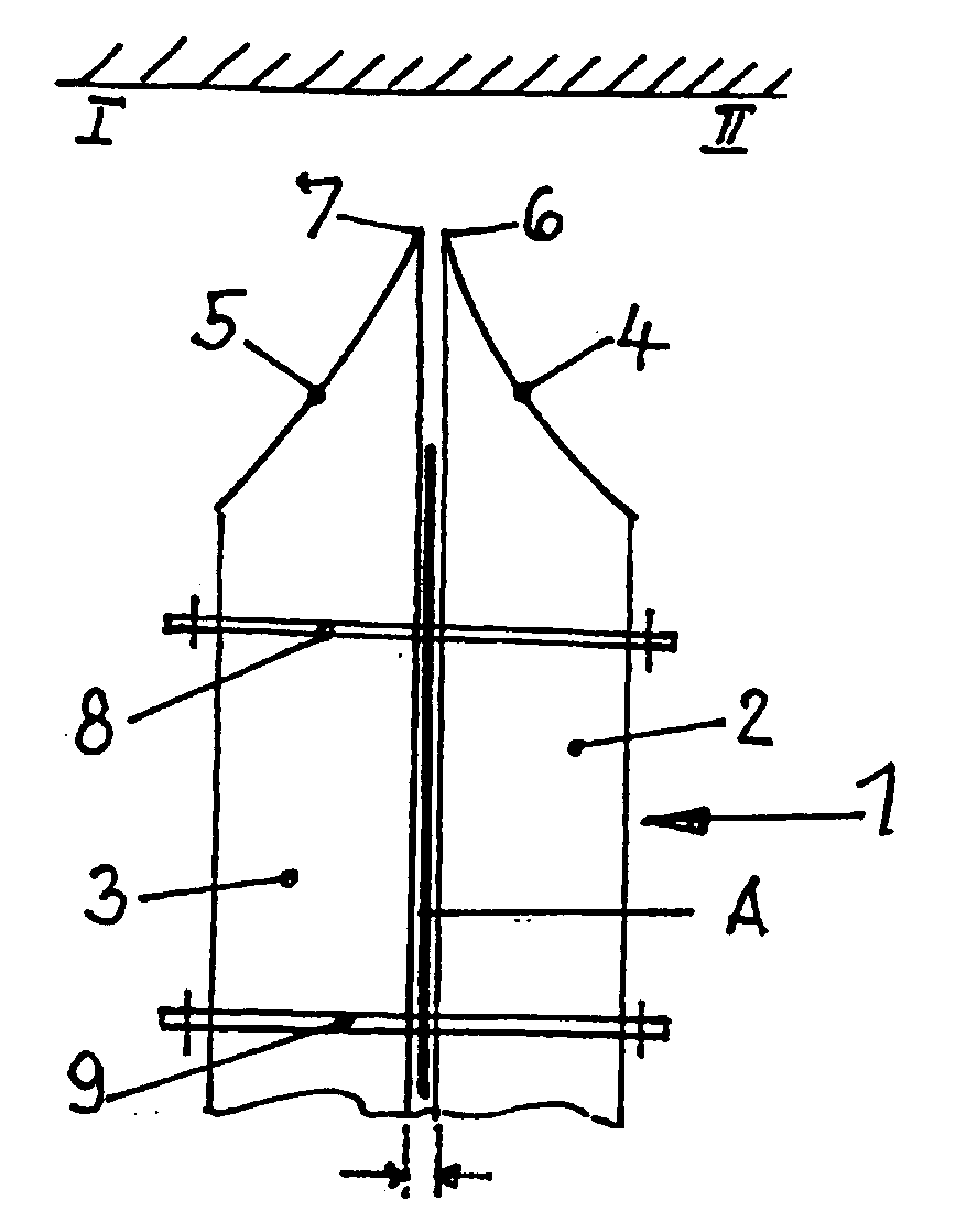
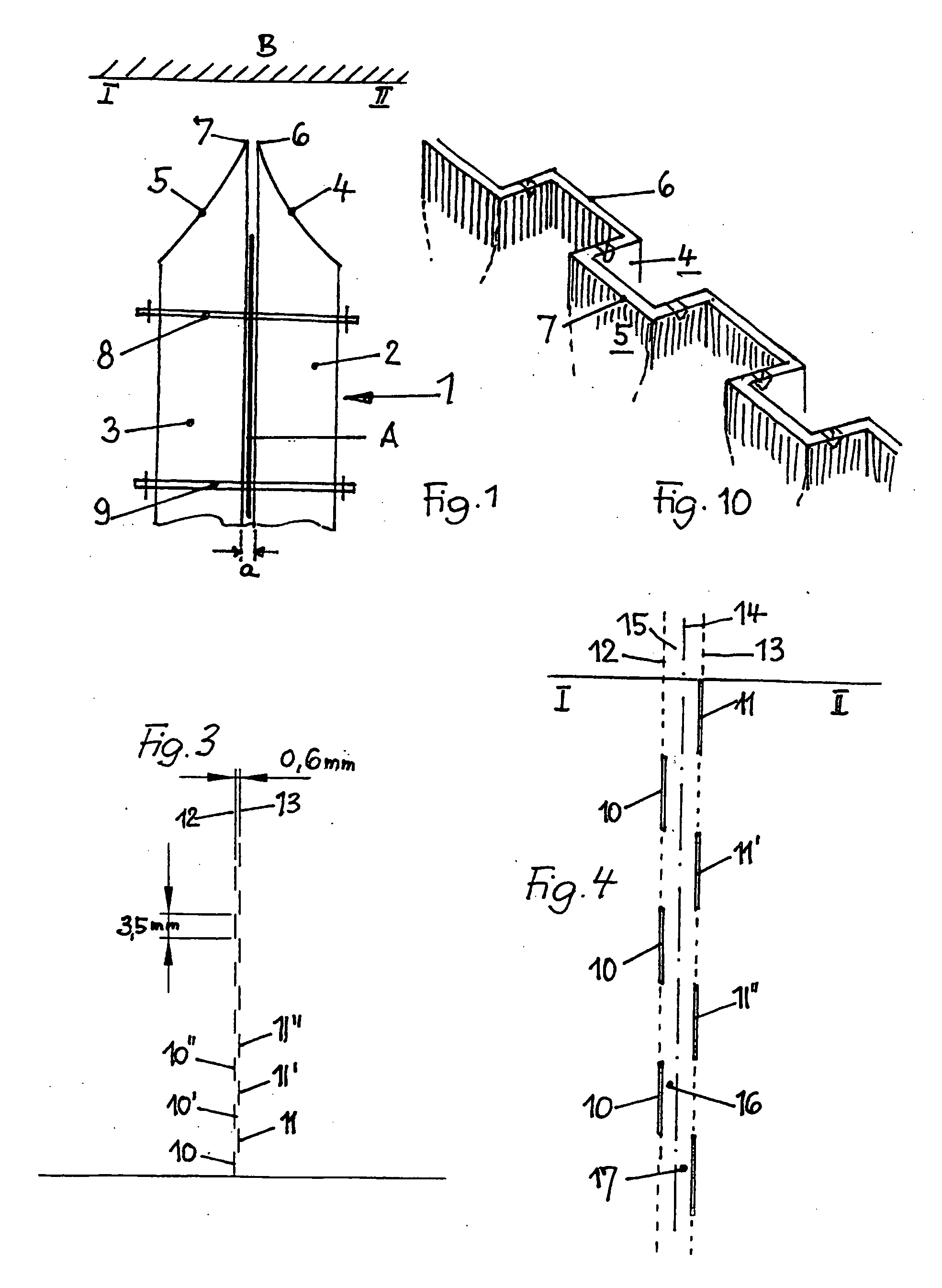
[0023] In FIG. 1 a double perforating knife 1 is shown, which consists of two individual perforating knives 2, 3. The knife teeth 4, 5 and the cutting edges 6, 7 are schematically shown. The two individual perforating knives 2, 3 have a distance a from each other at least at the cutting edges, this distance a can be adjusted according to the thickness of the material of the sheet B to be perforated, and can be varied by additional spacers A. The perforation knives are releasably fastened by screws 8, 9.

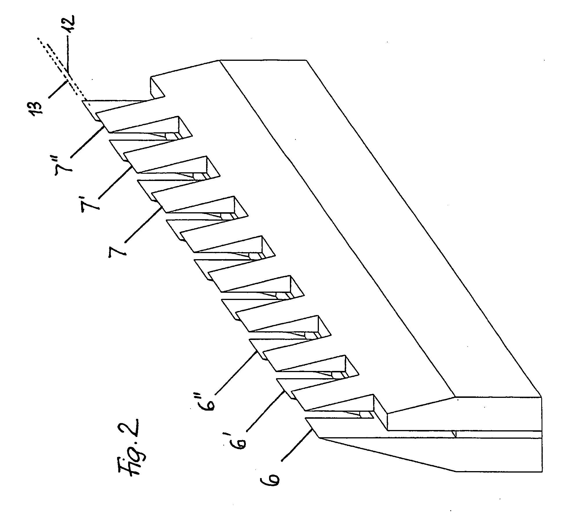
[0024] The double perforation tool 1 is shown in a perspective view in FIG. 2 showing its structure and its operation mode. The cutting edges or teeth 6, 6′, 6″, . . . are for punching the slots 10, 10′, 10″, . . . , the cutting edges or teeth 7, 7′, 7″. . . are for punching the slots 11, 11′, 11″, . . . according to FIG. 3. With a special embodiment of the invention the distance of the two perforation lines 12 and 13 is for example 0.6 mm, the length of a tooth 6 or 7 is for example...


PUM

PropertyMeasurementUnit
lengthaaaaaaaaaa
distanceaaaaaaaaaa
thicknessaaaaaaaaaa

Abstract

In order to produce an adhesive binding for bookbinding, in which the sheets, in letter paper format, are perforated on the folding edge, folded, provided with adhesive on the folding edge and assembled to form a book block, the perforating process is carried out on the folding edge in such a manner that two interrupted perforation lines are punched, these perforation lines being parallel at a short distance from one another, offset in a longitudinal direction and forming a widened folding edge. The punch locations of both perforation lines are, along the folding edge, offset by the length of one perforating tooth. The sheets, which are folded on the folding edge and which are assembled and squeezed to form a book block, are provided with the application of adhesive on surfaces, which are formed by the double perforating and which are assigned to one another, between full locations of one perforation line and full locations of the other perforation line.

Description

BACKGROUND OF THE INVENTION [0001] This invention refers to a process and a device for performing an adhesive binding. [0002] The process of adhesive binding of sheets to be combined into a book block is carried out in such a manner that the back of the block of sheets, which in their entirety form the book block, is provided with adhesive material and is pressed together. According to this process the adhesive material can flow only in a direction across the back into the edge areas of the sheets at the joint to a minimum extent so that the bonding area is very small and so that only a very limited degree of strength of the bonding area is obtained. [0003] A higher degree of strength is obtained by using the so-called fanning technique according to DE 103 41 493.2 with which the sheets forming the book block are fanned while the back of the not yet completed book block (in the form of the clamped sheets) is provided with adhesive material. By fanning the sheets the adhesive materia...

Claims


Application Information

Patent Timeline
Patent Type & Authority Applications(United States)
IPC IPC(8): B42C9/00B26F1/14B26F1/18B26F1/20B26F1/22
CPCB26F1/14B26F1/18B26F1/20B26F1/22Y10T156/1026Y10T156/1051Y10T156/1056Y10T156/1304B42C9/0081
Inventor SCHMIDKONZ, PETER
Owner SCHMIDKONZ PETER
Why Eureka
Try Eureka