Cervical Medical Device, System and Method

a medical device and cervical canal technology, applied in the direction of dilators, surgery, etc., can solve the problems of unintentional perforation of the uterine wall, additional visits to the doctor, and inconveniences associated with the use of misoprostol

Inactive Publication Date: 2007-02-08
HIBLER TIMOTHY B
View PDF22 Cites 33 Cited by
  • Summary
  • Abstract
  • Description
  • Claims
  • Application Information

AI Technical Summary

Problems solved by technology

Unfortunately, this method can be painful for the patient and often results in tearing of the cervical tissues, which causes bleeding and frequently leads to unintentional perforation of the uterine wall.
The problems associated with Laminaria are that it requires an additional visit to the doctor because the medical procedure to be performed must be done between 12 and 24 hours after the insertion of the Laminaria and there is no control of the final dilated diameter of the cervix.
There are however inconveniences associated with the use of Misoprostol.
Since it is a form of prostaglandin, it may also contribute to uterine cramping, which causes pain and discomfort.
If the cervix become too soft, establishing a seal on the hysteroscope on the day of the procedure may be problematic.
Like all drugs, there can be numerous side effects and complications associated with the use of Misoprostol.
This solution does indeed reduce the difficulties and complications mentioned above, but at the cost of a reduction in visual clarity.
Additionally, the small instruments that are required for these smaller hysteroscopes are inadequate for all but the most basic procedures a gynecologist performs.
These smaller scopes are thus restricted to limited visual diagnostic procedures only.
All of these distension media do provide at least one common challenge to the hysteroscopist: the need to contain them within the confines of the uterine cavity such that a slight positive intrauterine pressure is established.
This loss of fluid not only makes establishing and maintaining a positive pressure difficult, it also allows for a fairly significant volume of contaminated fluid to flow onto the operating room floor.
The flow of fluid onto the operation room floor represents a safety hazard for the operating room personnel and if the fluid being used is a non-electrolyte, it also poses a safety risk to the patient.
In the latter case, if enough non-electrolytic fluid is absorbed by the patient, it can cause a condition known as hyponatremia, which has a morbidity and mortality risk associated with it.
If fluid is lost to the drapes, floor, etc. this task becomes more difficult and less accurate.

Method used


Image

  • Cervical Medical Device, System and Method
  • Cervical Medical Device, System and Method
  • Cervical Medical Device, System and Method

Examples


Embodiment Construction

[0027] The following detailed description of the preferred embodiments presents a description of certain specific embodiments to assist in understanding the claims. However, one may practice the present invention in a multitude of different embodiments as defined and covered by the claims.

[0028] Referring more specifically to the drawings for illustrative purposes, the present invention is embodied in the devices generally shown in the Figures. It will be appreciated that the devices may vary as to configuration and as to details of the parts, and that the methods may vary as to the specific steps and sequence, without departing from the basic concepts as disclosed herein.

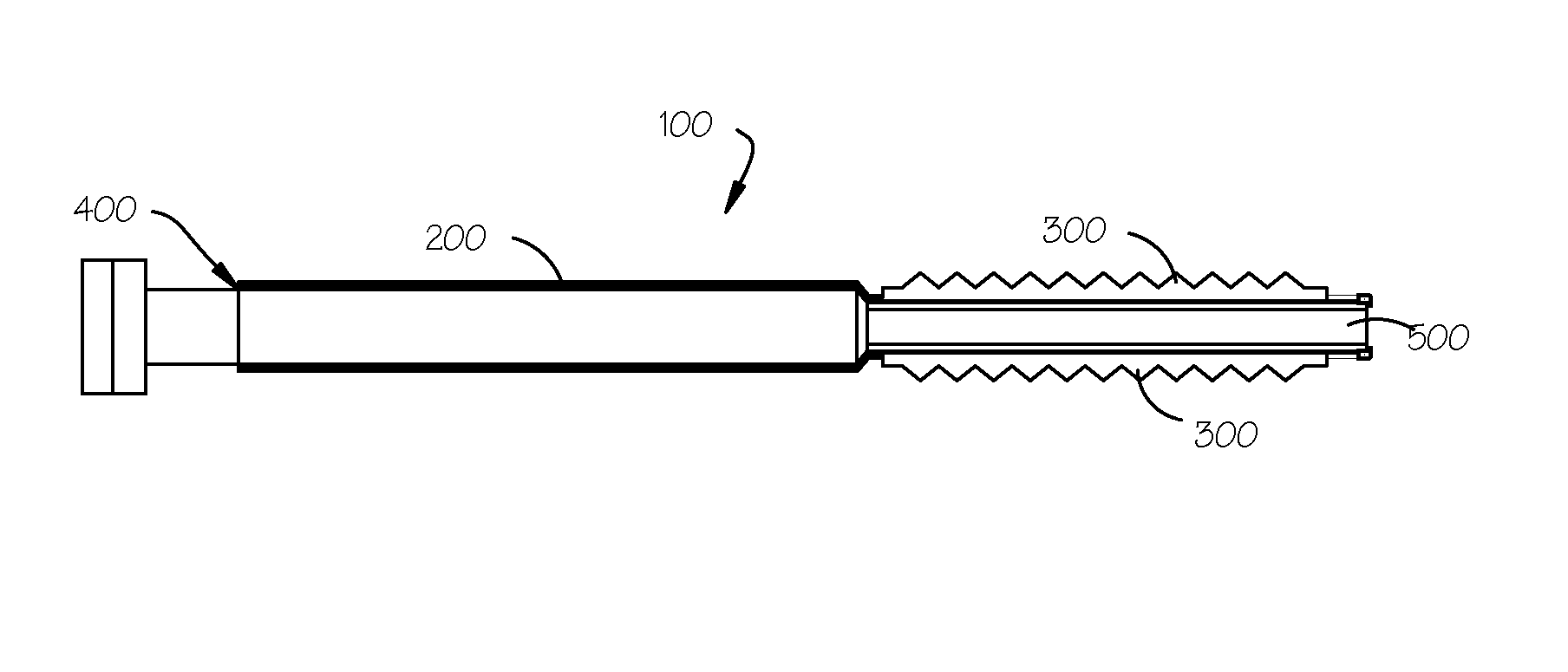
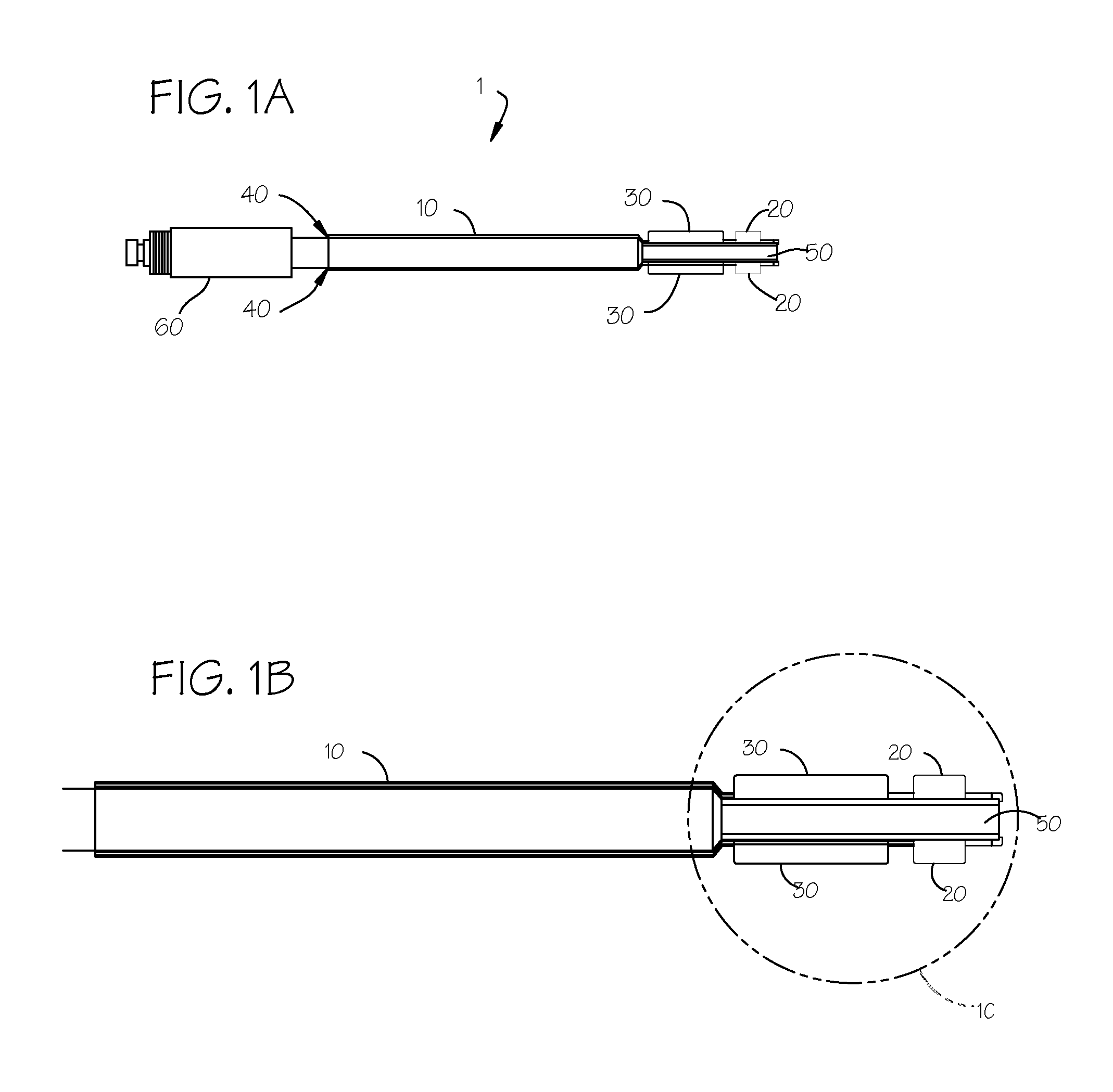
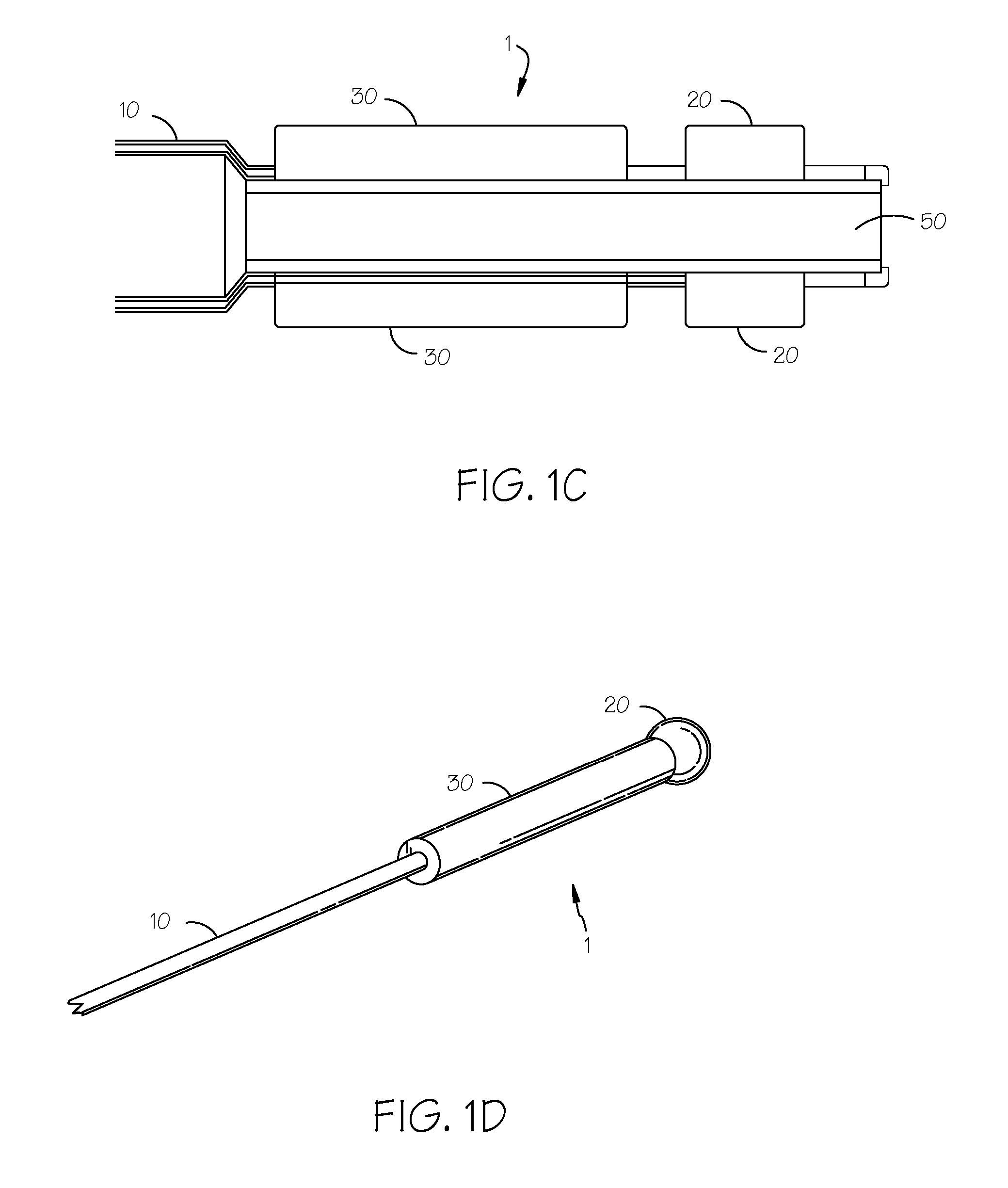
[0029] One embodiment of the invention is illustrated by reference to FIGS. 1A-1D. As shown in FIGS. 1A-1C, the device 1 has an elongated member 10 having a proximal end and a distal end. Preferably, the elongated member 10 is a slender, rod-like instrument. The elongated member 10 preferably is about 15-30 cm lo...


PUM


Abstract

A device and method for dilating a cervical canal. The device includes an elongated member with an expandable anchoring component attached to its distal tip. An expandable dilating member is attached to the elongated member proximally of the anchoring component for dilating the cervical canal. The anchoring component can be expanded after insertion of the device into the cervical canal to correctly position the device relative to the canal. A device and method for sealing a cervical canal is also provided. The device includes a tube having an expandable seal assembly attached to its distal end. The seal assembly has a ridged or corrugated surface when it is in an expanded condition to provide a seal for the cervical canal.

Description

[0001] This application is a continuation of U.S. App. 10 / 719,500 filed Nov. 21, 2003, now U.S. Pat. No. 7,105,007, which claims priority to U.S. Provisional App. 60 / 428,397, filed on Nov. 21, 2002.FIELD OF THE INVENTIONS [0002] The present invention relates to medical devices, systems, and methods for dilating a cervical canal in a female patient. BACKGROUND OF THE INVENTIONS [0003] The cervix is a dense yet distendible organ that responds to internal pressure (within the endocervical canal) by expanding within anatomical limits to assume the diameter or shape of the item causing the pressure. If this pressure is applied gradually, the tissues of the cervix will usually experience minimal damage. It has been observed that if the pressure is maintained for a short period of time, the cervix will temporarily fix itself to that diameter. In other words, the cervix will temporarily stay open even after the pressure has been removed. It will then gradually return to its normal resting d...

Claims


Application Information

Patent Timeline
Patent Type & Authority Applications(United States)
IPC IPC(8): A61M29/00A61B
CPCA61M29/02
Inventor HIBLER, TIMOTHY B.
Owner HIBLER TIMOTHY B
Why Eureka
Try Eureka