Integrated center rail dispenser

a dispenser and center rail technology, applied in the field of refrigeration devices with dispensers, can solve the problem that the mullion assembly cannot be accessible from the exterior of the appliance, and achieve the effects of reducing the wiring and plumbing complexity of the refrigeration appliance, reducing the cost of manufacturing, and facilitating service calls

Inactive Publication Date: 2007-02-15
WHIRLPOOL CORP
View PDF9 Cites 25 Cited by
  • Summary
  • Abstract
  • Description
  • Claims
  • Application Information

AI Technical Summary

Benefits of technology

[0010] In an embodiment, as many of the water components of the appliance, such as all of the water components are located in the rail. In an embodiment, as many of the electronic control components of the appliance, such as all of the electronic control components, are located in the rail. Such an arrangement will reduce the wiring and plumbing complexity of the refrigeration appliance, and will also allow for several different models of the appliance to be made from a single liner and shell configuration, with only the rail with its various water and electronic control components changed between models, to provide different combinations of features in different models, while allowing for manufacturing flexibility. Further, if a water component or a control component fails or needs repair, the entire rail can be removed and replace with a new rail, so that the components can be repaired at a repair facility, rather than in the field, resulting in quicker and more efficient service calls.

Problems solved by technology

The mullion assembly is not accessible from the exterior of the appliance, and can only be accessed when the appliance door is open.

Method used


Image

  • Integrated center rail dispenser
  • Integrated center rail dispenser
  • Integrated center rail dispenser

Examples


Embodiment Construction

[0025] The present invention finds particular utility in a domestic refrigerator having a fresh food compartment located below a freezer compartment, however, the invention can be used in other refrigeration appliances having different configurations. In order to provide a disclosure of the invention, the embodiment of a refrigeration appliance with a freezer compartment located above a fresh food compartment is shown and illustrated, it being understood that the scope of the invention is not limited to such an arrangement.

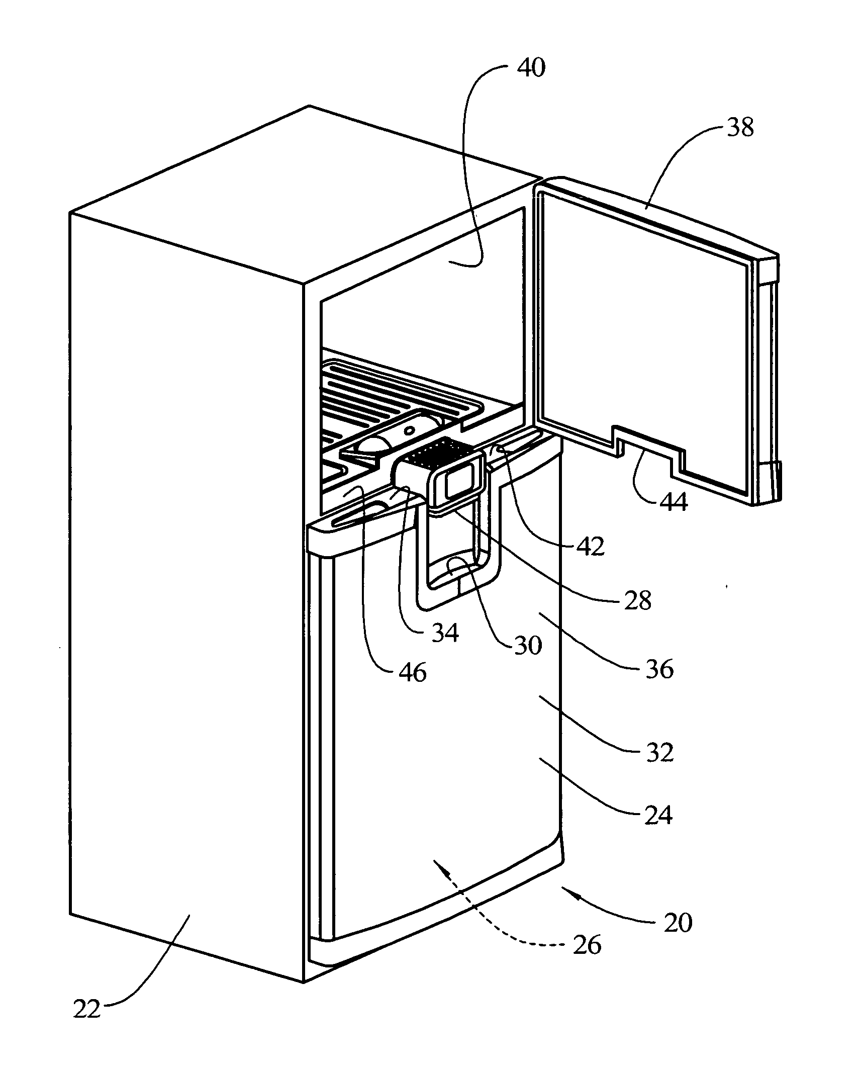
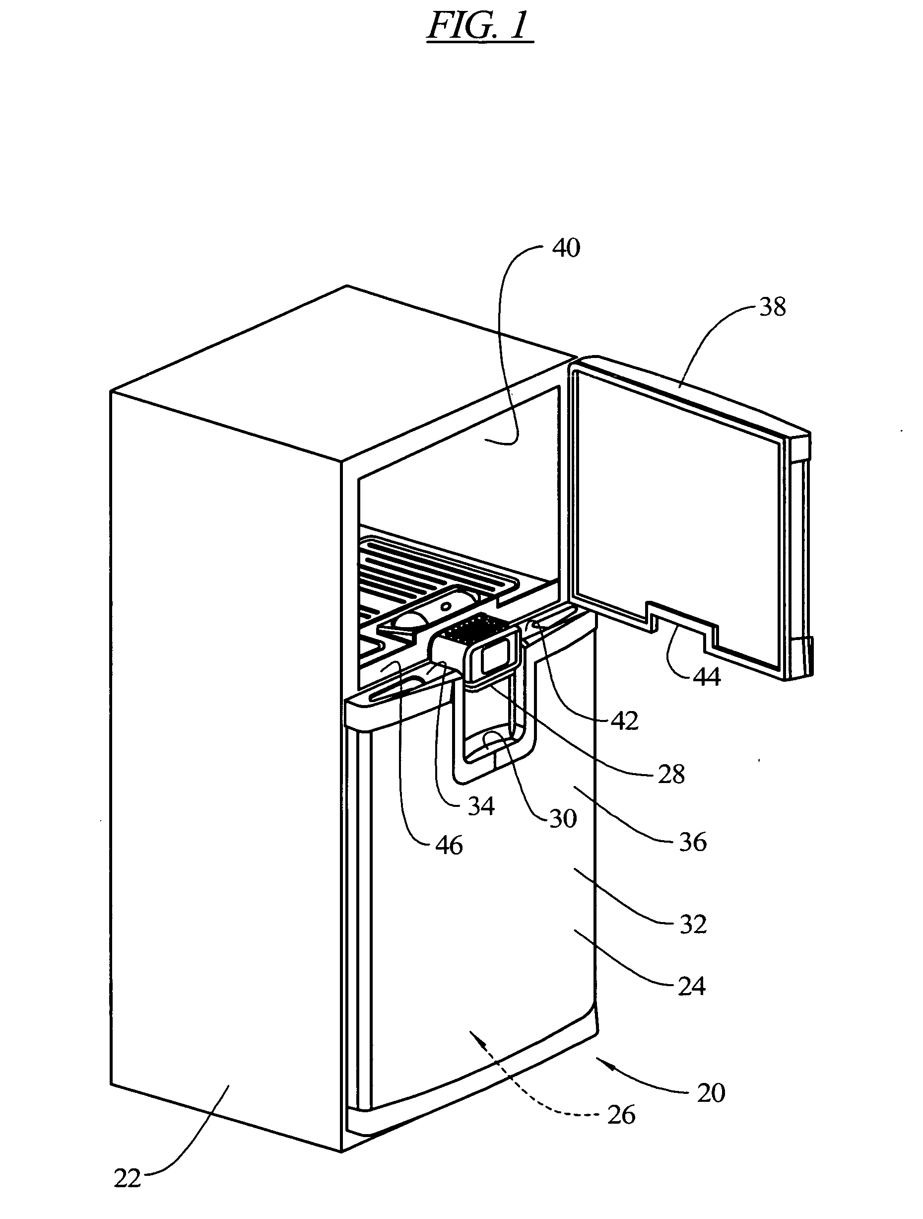
[0026]FIG. 1 illustrates a refrigeration appliance 20 which includes a cabinet 22 with an openable door 24 providing access to a refrigeration compartment 26. A dispenser 28, such as a water dispenser, may be contained in the refrigeration appliance 20, accessible from an exterior of the refrigeration appliance while the door 24 is closed. The dispenser 28 is arranged to be stationary relative to the refrigeration appliance 20 while the door 24 is open or closed....


PUM


Abstract

A refrigeration appliance is provided which includes a cabinet with a first openable door providing access to a first refrigeration compartment and a second openable door providing access to a second refrigeration compartment. The second openable door has a portion thereof positioned below a portion of the first openable door. A rail separates the first refrigeration compartment and the second refrigeration compartment. A water dispenser is contained in the rail, as well as electronic controls for the refrigeration appliance. The dispenser is arranged to be stationary relative to the refrigeration appliance while the doors are open or closed. The rail may be removed and replaced, and with the water and electronic controls located in the rail, repairs are performed more efficiently and flexibility in manufacturing is enhanced. A drip tray is formed in an exterior side of the second openable door below the dispenser. When the door is opened, the drip tray moves away from the dispenser, permitting the dispenser to be used with larger receptacles than can be accommodated with the drip tray under the dispenser.

Description

BACKGROUND OF THE INVENTION [0001] The present invention relates generally to refrigeration devices with dispensers, such as water dispensers. [0002] Refrigeration appliances with dispensers, such as door mounted water dispensers are well known, such as disclosed in U.S. Pat. Nos. 6,804,974 and 6,763,976. In such arrangements, the dispenser is located in a door of the appliance, accessible only from an exterior of the appliance. This requires that water and electronics pathways are routed from the back of the refrigerator, then inside the cabinet (to the cooling reservoir for the water), back outside the cabinet (room temperature) to the bottom hinge area. Depending on the swing of the door selected by the user, the water and electric lines are routed through one of the hinges and into the door, past special skirts to prevent wear to the lines when the door opens and closes. This type of assembly requires multiple sub-assemblies and routing of both water and electrical lines along t...

Claims


Application Information

Patent Timeline
Patent Type & Authority Applications(United States)
IPC IPC(8): B67D5/62F25D11/02B67D99/00B67D7/80
CPCF25D23/02F25D23/069F25D23/126F25D2400/40F25D2400/04F25D2400/36F25D27/00
Inventor EGAN, MARTIN SHAWNGILMAN, BOBBIE J.
Owner WHIRLPOOL CORP
Why Eureka
Try Eureka