Door operating mechanism and unit

a technology of operating mechanism and rotary gear, which is applied in the direction of passenger space, transportation and packaging, manufacturing tools, etc., can solve the problems of reducing affecting the efficiency of assembly, and not attractive and sophisticated in appearance, so as to improve assembly efficiency, reduce costs, and simplify construction

Inactive Publication Date: 2007-02-15
NIFCO INC
View PDF15 Cites 48 Cited by
  • Summary
  • Abstract
  • Description
  • Claims
  • Application Information

AI Technical Summary

Benefits of technology

[0024] In another noted embodiment, the mechanism according to the present invention further simplifies the construction by employing a movable part as a support structure for the second gear.
[0025] In yet another embodiment, the door operating unit includes biasing means, lock means and damper means, and the present invention not only has the advantages of the aforementioned door operating mechanism, but also improves efficiency in assembly and reduces costs by allowing the rotary gear of the mechanism to be replaced with a damper means.
[0026] In yet another embodiment, the present invention includes a guide means to further improve the stability in the switching operation.

Problems solved by technology

A door operating mechanism, including a door that is rotatably switched between the closed and open positions relative to the opening of a box-shaped base, via a shaft or the like, is not attractive and is less sophisticated in appearance, as the door projects extensively from the base in the open position.
This may potentially damage the section or the support of the rotary gear 7 that is engaged.

Method used


Image

  • Door operating mechanism and unit
  • Door operating mechanism and unit
  • Door operating mechanism and unit

Examples


Embodiment Construction

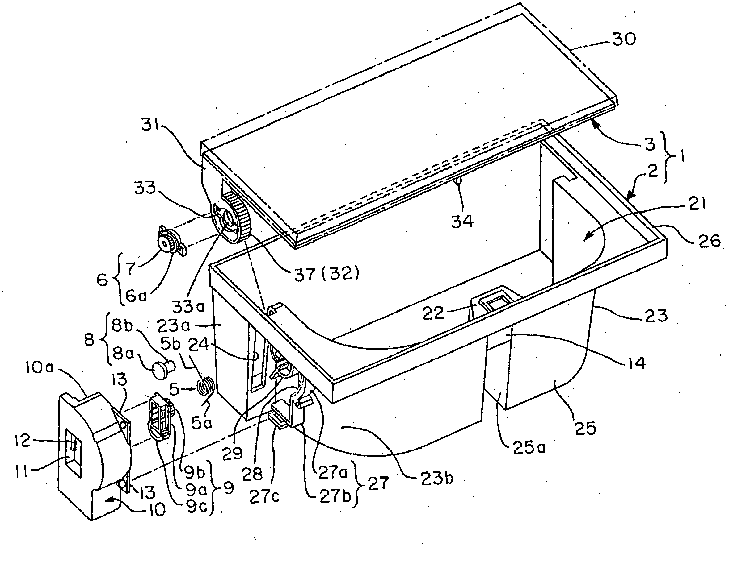
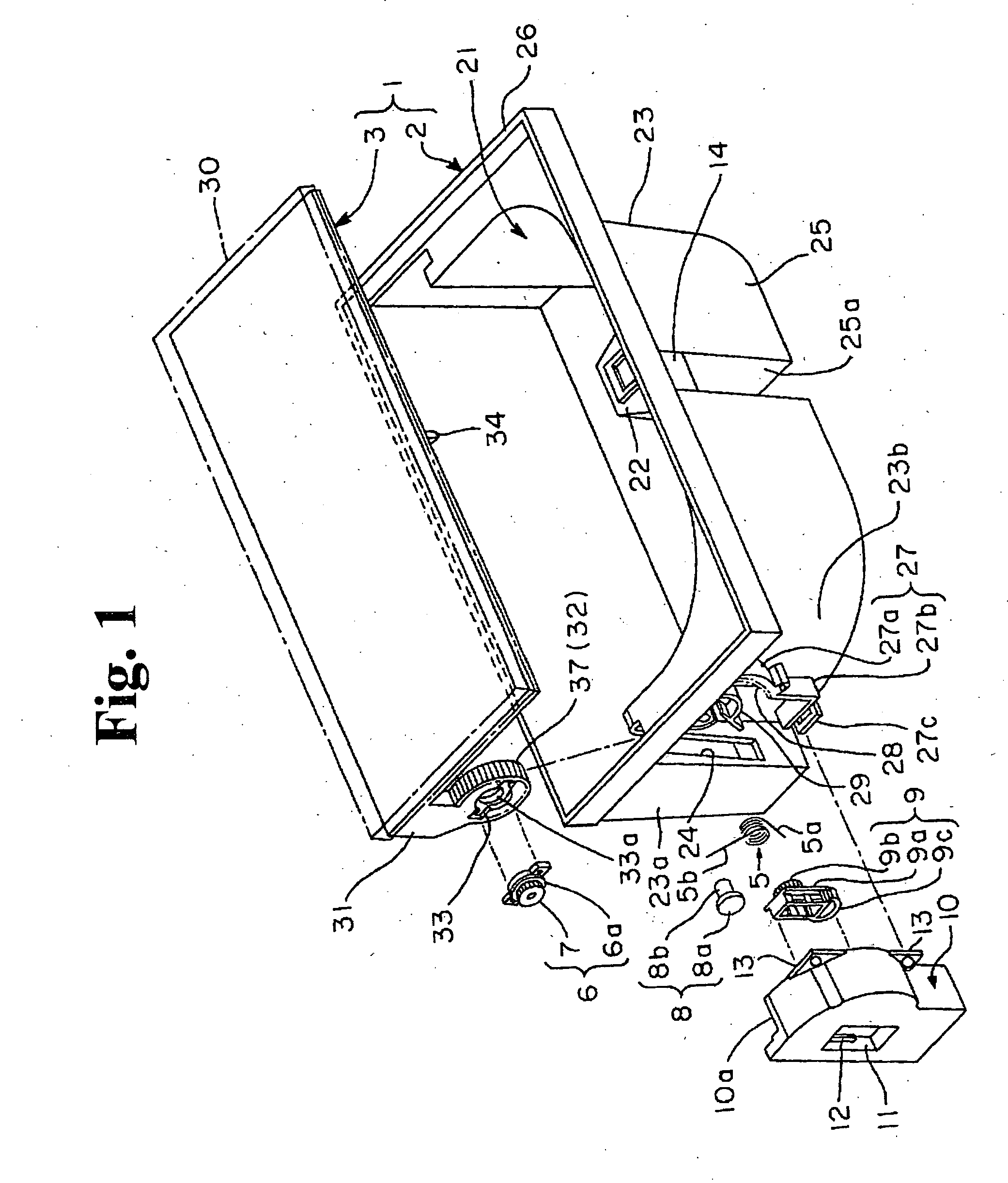
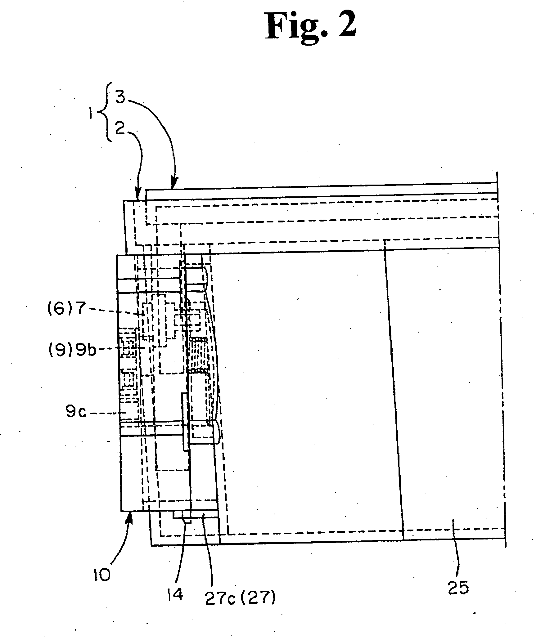
[0038] Preferred embodiments of the door operating mechanism of present invention are explained while referring to the figures. The reference numerals and drawings are not meant to limit the technical scope of the present invention.

[0039] In FIGS. 1-7(b), the members that are the same as or similar to those in the conventional mechanism shown in FIGS. 8(a) and 8(b) are denoted with the same reference numerals. In the explanation provided below, the overall mechanism is initially summarized in an overview, with the primary operation disclosed in reference to the disclosed embodiments.

[0040] Beginning with the overview, the door operating unit is exemplarily shown as a box 1 that comprises a box-shaped base 2 and a door 3 that opens and closes the upper opening of the box-shaped base 2. The unit includes a biasing means 5 to bias the door 3 from the closed position towards the open position, a lock means 4 to lock or unlock the door 3 in the closed position, covering the upper openi...


PUM


Abstract

A door operating mechanism is provided for rotatably switching a door relative to a base between a closed position and an open position. A sector gear is disposed in a support arm projected from the door. A rotary gear is disposed substantially in the center of the arc of the sector gear. A first gear of the base has internal teeth disposed to engage the sector gear. A second gear of the base is resiliently and displaceably disposed to engage the rotary gear. The door is rotatably disposed along a track corresponding to the first gear via engagements between the first gear and the sector gear, and engagements between the second gear and the rotary gear. A load received by the door in the closed position towards the bottom of the base is absorbed by resilient displacement of the second gear.

Description

BACKGROUND OF THE INVENTION AND RELATED ART STATEMENT [0001] The present invention relates to a door operating mechanism for operating a door relative to a box-shaped base, and a unit including the same. As used herein, the term “box-shaped base” is interpreted broadly to include various types of storage body, housing and the like, and the term “door” is also interpreted broadly to include lid, cover and the like. [0002] A door operating mechanism, including a door that is rotatably switched between the closed and open positions relative to the opening of a box-shaped base, via a shaft or the like, is not attractive and is less sophisticated in appearance, as the door projects extensively from the base in the open position. [0003] Such a door operating mechanism and the unit including the same, as shown in FIGS. 8(a) and 8(b), were developed by the present inventors in their effort to remedy such shortcomings, as provided in Japanese Patent Laid-open Publication No. 2003-129742 (“JP...

Claims


Application Information

Patent Timeline
Patent Type & Authority Applications(United States)
IPC IPC(8): B60R7/06B65D43/22
CPCB60R7/06Y10T16/541B65D43/26
Inventor FUKUO, MICHIHIRO
Owner NIFCO INC
Why Eureka
Try Eureka