Optical-emission-signal output apparatus
- Summary
- Abstract
- Description
- Claims
- Application Information
AI Technical Summary
Benefits of technology
Problems solved by technology
Method used
Image

Examples
first embodiment
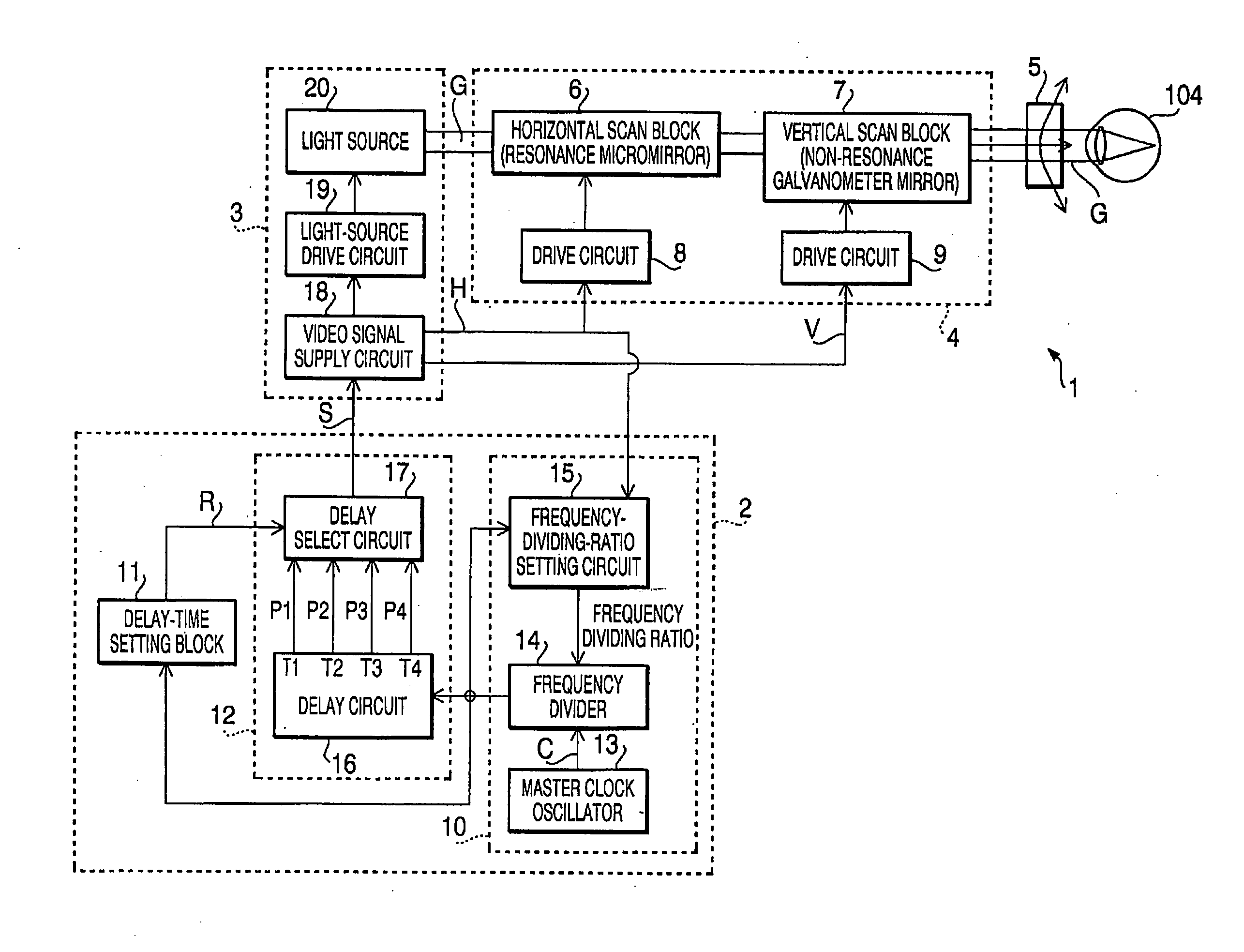
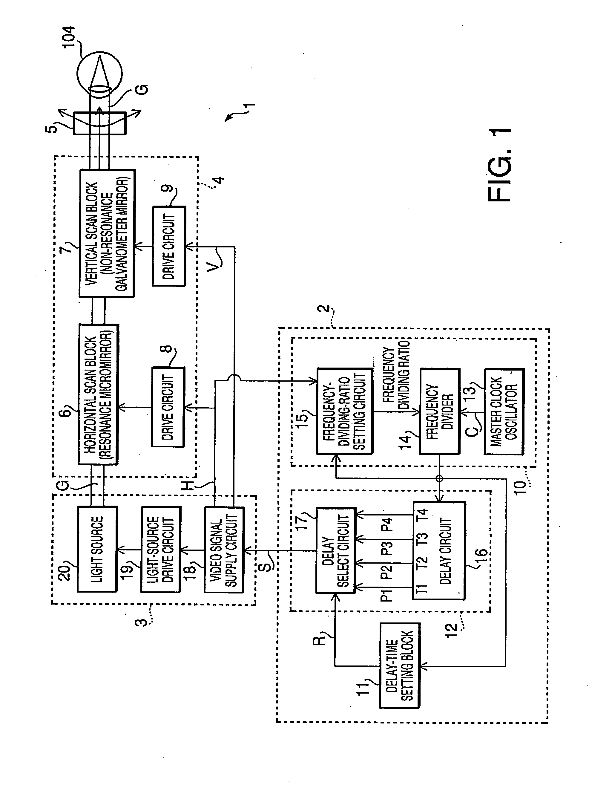
[0026]FIG. 1 is a block diagram showing an image display apparatus 1 according to a first embodiment of the present invention. The image display apparatus 1 is an image display apparatus provided with an optical-emission-signal output apparatus 2.
[0027] The image display apparatus 1 includes an optical-emission unit 3 for outputting light, an optical-scan unit 4 for scanning light output from the optical-emission unit 3, and a projection unit 5 for projecting light scanned by the optical-scan unit 4 onto the retina in an eye 104 of the observer, a screen, or the like. The image display apparatus 1 also includes the optical-emission-signal output apparatus 2.
[0028] The optical-scan unit 4 includes a horizontal scan block 6 and a vertical scan block 7. The horizontal scan block 6 scans light output from the optical-emission unit 3 horizontally, as driven by a drive circuit 8. The vertical scan block 7 scans light output from the optical-emission unit 3 vertically, as driven by a dri...
second embodiment
[0049]FIG. 5 is a block diagram showing an image display apparatus 1B according to a second embodiment of the present invention. The image display apparatus 1B is an image display apparatus provided with an optical-emission-signal output apparatus 2B. In FIG. 5, components equivalent to those of the image display apparatus 1 shown in FIG. 1 are denoted by the same reference symbols. A description of the components equivalent to those in the first embodiment will be omitted. The image display apparatus 1B of the second embodiment is distinguished by having a frequency-dividing-ratio-and-delay-time setting unit 21. The frequency-dividing-ratio-and-delay-time setting unit 21 includes a frequency-dividing-ratio setting circuit 15, a delay-time setting unit 31, a memory 22, and a control block 23 for controlling the frequency-dividing-ratio setting circuit 15, the delay-time setting unit 31, and the memory 22. The frequency-dividing-ratio setting circuit 15 has the same structure as the ...
PUM
 Abstract
Description
Claims
Application Information
 - R&D Engineer
- R&D Manager
- IP Professional
- Industry Leading Data Capabilities
- Powerful AI technology
- Patent DNA Extraction
Browse by: Latest US Patents, China's latest patents, Technical Efficacy Thesaurus, Application Domain, Technology Topic.
© 2024 PatSnap. All rights reserved.Legal|Privacy policy|Modern Slavery Act Transparency Statement|Sitemap