Image editing apparatus and control method for the same, computer program, storage media

a technology of image editing and control method, which is applied in the direction of instruments, computing, electric digital data processing, etc., can solve the problems of image capture sections, exposed to the outside atmosphere, and become an issu

Inactive Publication Date: 2007-02-15
CANON KK
View PDF5 Cites 15 Cited by
  • Summary
  • Abstract
  • Description
  • Claims
  • Application Information

AI Technical Summary

Benefits of technology

[0014] In consideration of the above, the present invention enables dust removal to be effectively performed even when using operation history on images containing different pictures.

Problems solved by technology

One structural problem of digital single-lens reflex cameras is that their image capturing sections which are composed of image capturing sensors and the like are exposed to the outside atmosphere when changing lenses, unlike cameras of the noninterchangeable lens type (integrated type).
In addition, while (1) is automatically processed in its entirety and therefore enables operation costs to be minimized, analysis processing such as preparing an image for dust area identification becomes an issue, and risks such as image quality deterioration due to erroneous decisions exist.
On the other hand, although (2) requires high operation costs since area designation is performed entirely by hand, output results may be reliably matched with the application user's intentions.
However, even when processing a plurality of images, general image processing applications require processing from scratch for every image, and are therefore bothersome.
However, while methods using operation history as-is may be effective on images which contain identical pictures, it is highly likely that the use of such methods on images which contain different pictures will result in inappropriate processing.
This is an issue which will not be solved even if the rotation directions of images are brought into consideration.

Method used


Image

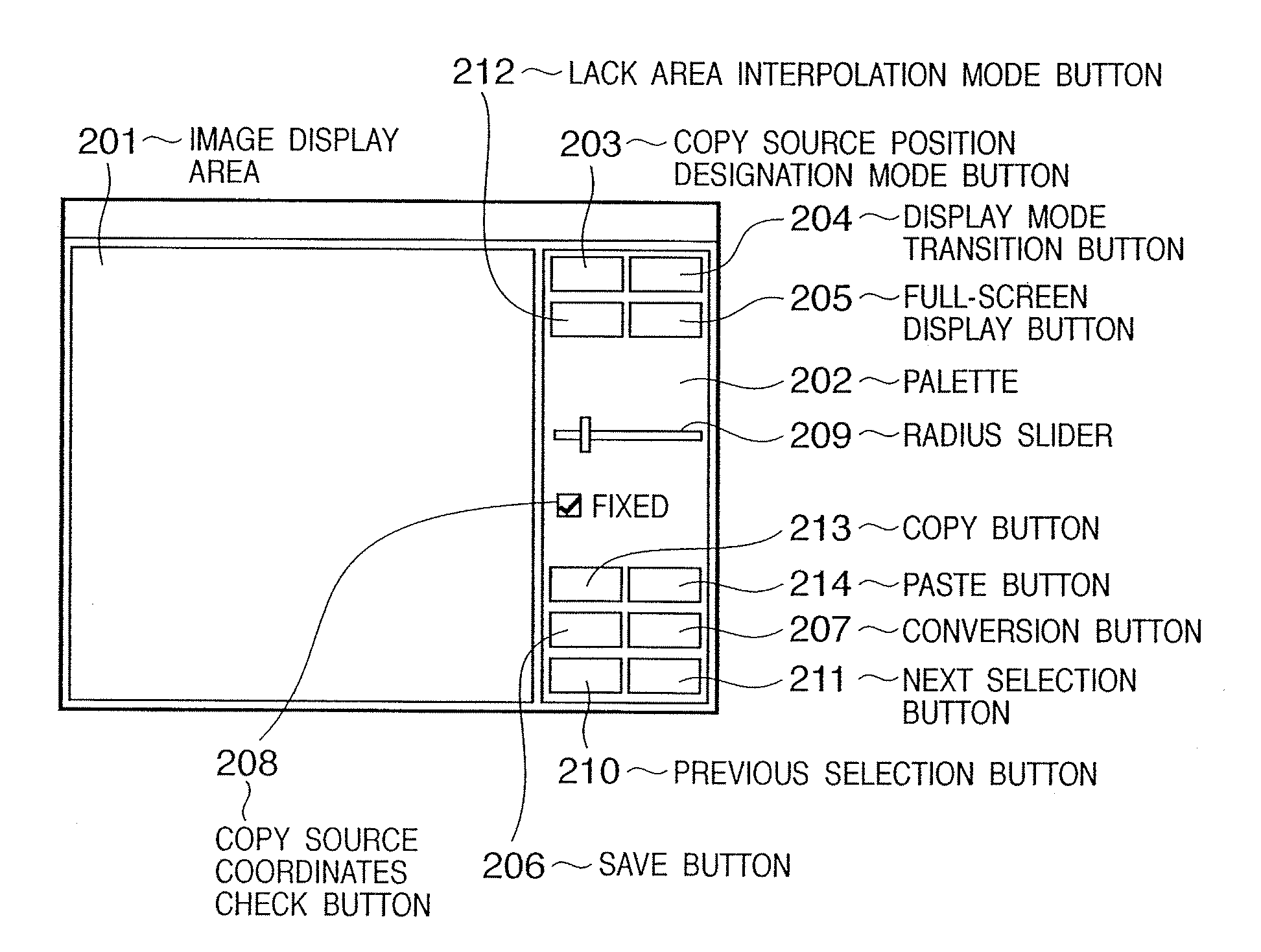
  • Image editing apparatus and control method for the same, computer program, storage media
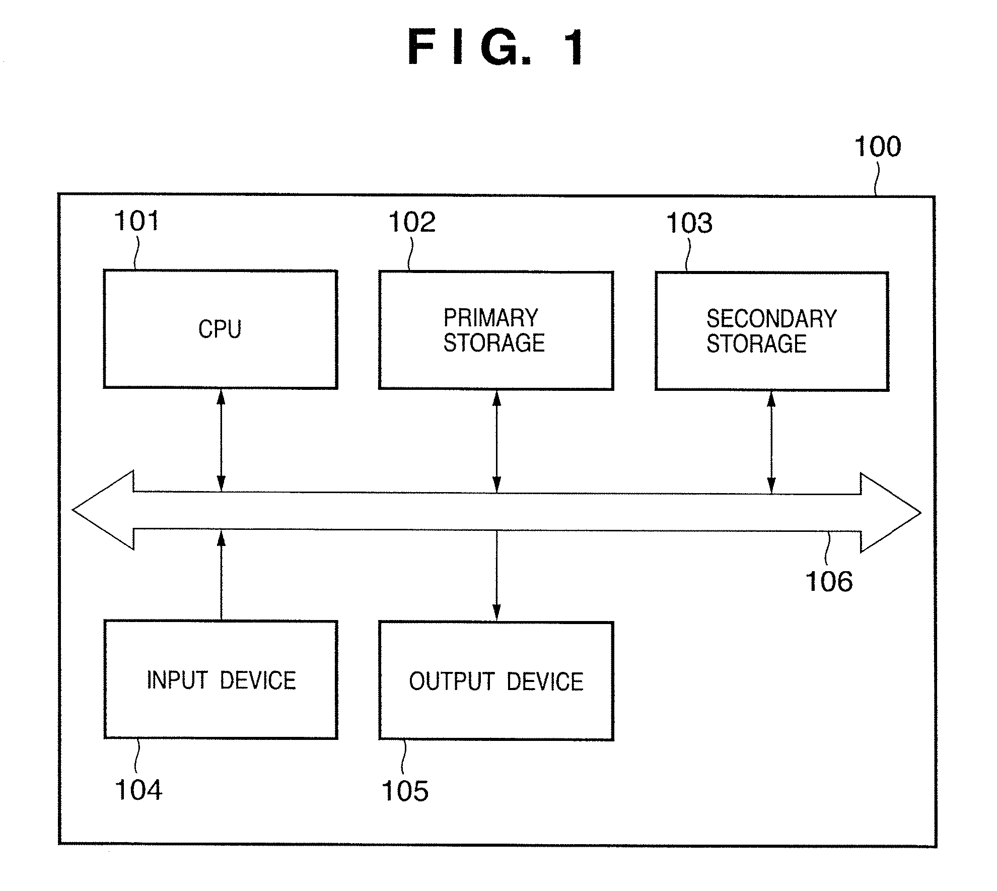
  • Image editing apparatus and control method for the same, computer program, storage media
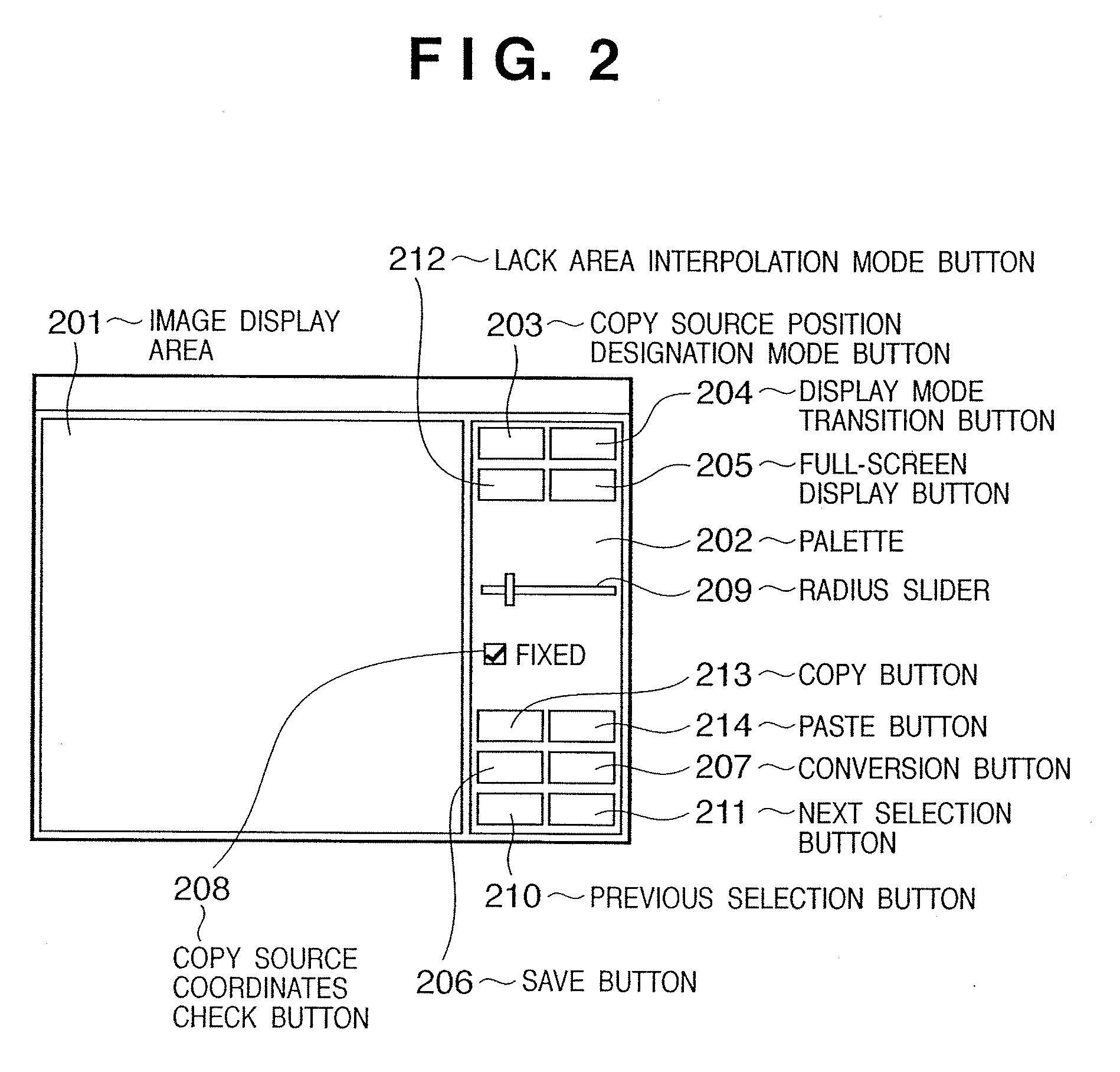
  • Image editing apparatus and control method for the same, computer program, storage media

Examples


first embodiment

[0117] In the above-described embodiment which forms the basis of the present invention, a case was explained in which the display mode was switched back to the fit mode 401 (for instance, step S807 in FIG. 8) when either a file was designated by an application or when an image to be edited 300 was changed using the previous selection button 210 or the like. Alternatively, in the present first embodiment, an appropriate area is displayed without switching display modes.

[0118] In addition, in the above-described embodiment, a GUI used for performing dust reduction processing when dust attached to a sensor is incorporated into image data has been described. Although there are cases where dust on the sensor moves slightly due to impact caused by the shutter and the like, it is well-known that there is a high probability that the dust will be incorporated in the same position through consecutively shot image data.

[0119] In consideration of the above, for the present embodiment, displa...

second embodiment

[0128] In the present embodiment, a method will be described in which dust reduction processing is performed in a more efficient manner by adding a display position assist function to the first embodiment. In addition to the configuration of the first embodiment, the present embodiment comprises a display coordinates table, a display coordinates table update flag, and a display position ID. A display position ID is information corresponding to a sequence in which image processing has been performed.

[0129] A display coordinates table is shown in FIG. 14. To begin with, a display coordinates table 1400 includes an image rotation direction 1401 of the image to be edited 300. The display coordinates table 1400 stores a double-precision floating-point number display coordinates array 1403 in which a coordinates array retrieved from the processing information stack 304 of the image to be edited 300 is normalized to [0.0, 1.0] using the width and height of the image to be edited 300, and ...

third embodiment

[0144] In the present embodiment, a description will be provided on the expansion of the display position assist function described in the second embodiment. Image editing apparatuses corresponding to the aforementioned first and second embodiments are configured to display areas outside of an image during same size mode. However, there are many applications which do not display outside-of-image areas even in same size mode when the size of the image to be edited is greater than the display area size. In such cases, as shown in FIG. 20, display positions are controlled so that no outside-of-image areas exist.

[0145]FIG. 20 is a diagram showing an outline of display position compensation processing. In FIG. 20, reference numeral 300 denotes an image to be edited. Reference numeral 2001 denotes coordinates designated as the center of the display area within the image to be edited 300. The display area designated based on the coordinates 2001 will resemble the area shown as reference n...


PUM


Abstract

The present invention enables dust removal to be effectively performed even when using operation history on images containing different pictures. An image editing apparatus including a storage unit for storing a plurality of image data to be edited and a display unit for displaying the image data to be edited, the image editing apparatus comprising: an image processing unit adapted to perform image processing on the image data to be edited; a history storage unit adapted to store information regarding processing history of image data to be edited which have previously undergone image processing; a position obtaining unit adapted to obtain position information regarding a position to where the image processing had been applied from the processing history information; and a display controller adapted to cause a portion, to which the image processing would be applied among the images to be edited, to be displayed on a display area for images to be edited on the display unit, based on the position information.

Description

BACKGROUND OF THE INVENTION [0001] 1. Field of the Invention [0002] The present invention relates to an image editing apparatus and control method for the same, computer program, and storage media. [0003] 2. Description of the Related Art [0004] One structural problem of digital single-lens reflex cameras is that their image capturing sections which are composed of image capturing sensors and the like are exposed to the outside atmosphere when changing lenses, unlike cameras of the noninterchangeable lens type (integrated type). Therefore, dust sticks to lowpass filters and the like on the image sensors, and is eventually incorporated into image data. While hardware support is essential in solving such dust problems, in order to rescue image data shot by cameras without such countermeasures in place, support by PC software (PC applications) is effective at the present moment. [0005] Possible methods for solving the dust problem using PC applications include: [0006] (1) Automatic dus...

Claims


Application Information

Patent Timeline
Patent Type & Authority Applications(United States)
IPC IPC(8): H04N1/40
CPCH04N1/4097H04N1/40093
Inventor KOTANI, TAKUYA
Owner CANON KK
Why Eureka
Try Eureka