Light scanning apparatus, method of controlling the same and image forming apparatus equipped with the same
a technology of light scanning apparatus and image forming apparatus, which is applied in the field of light, can solve the problems of destroying the oscillation mirror, not being able to enter amplitude control, and failing to output the indicative detection signal of light detecting sensors, so as to prevent the destruction of the oscillation mirror
- Summary
- Abstract
- Description
- Claims
- Application Information
AI Technical Summary
Benefits of technology
Problems solved by technology
Method used
Image
Examples
first embodiment
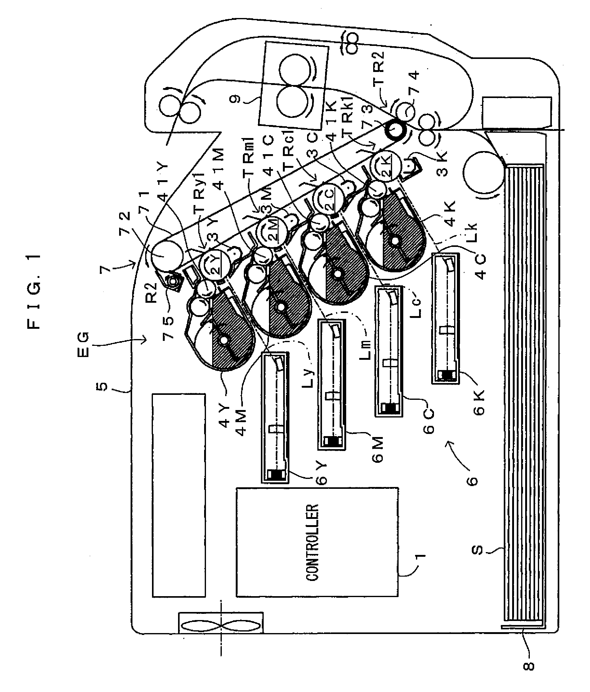
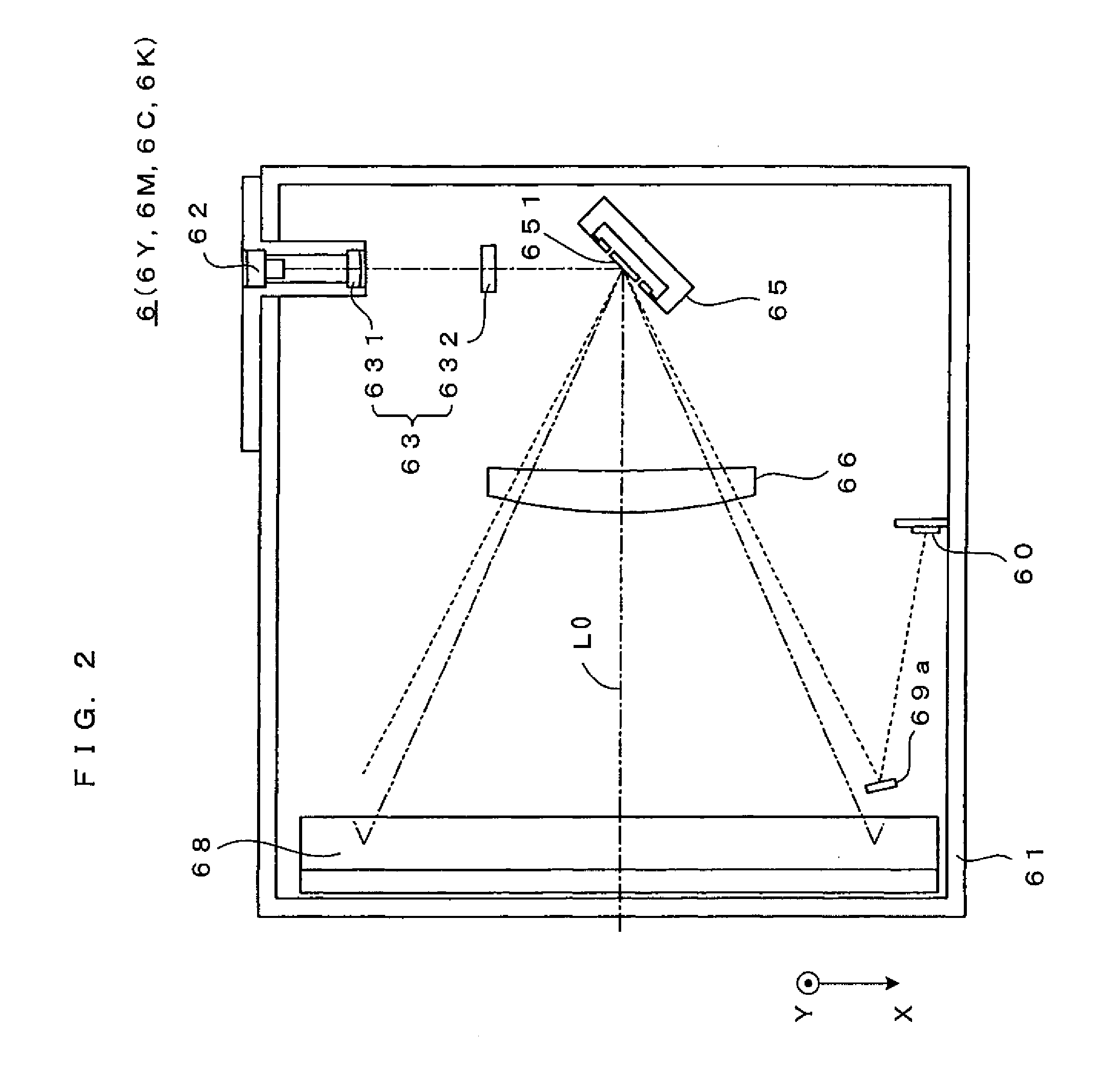
[0029]FIG. 1 is a diagram showing an image forming apparatus according to a first embodiment of the invention. This image forming apparatus is a so-called tandem color printer wherein photosensitive members 2Y, 2M, 2C, 2K for four colors of yellow Y, magenta M, cyan C and black K, as latent image carriers, are juxtaposed in an apparatus body 5. The apparatus is adapted to form a fill-color image by superimposing toner images on the individual photosensitive members 2Y, 2M, 2C, 2K, or to form a monochromatic image using only the toner image of black (K). The image forming apparatus operates as follows. When an external apparatus such as a host computer applies an image forming command to a controller 1 in response to a request from a user wanting to form an image, the controller 1 sends image signals, a reference signal, control signals and the like. In response to the signals from the controller 1, individual parts of an engine section EG operate to form the image corresponding to t...
second embodiment
[0059] While amplitude control is performed normally, the output timing gap Tnp between the first and the second detection signals is approximately constant and the maximum angle of amplitude θmax is at the amplitude target value. However, if the mirror drive controller 111 feeds an improper mirror drive signal to the operating section 652 of the deflector 65 under the influence of a noise or disturbance, the angle of amplitude of the deflector 65 could significantly change. The influence of a noise or the like in particular may vibrate the deflector 65 further. Noting this, the second embodiment requires monitoring a change of the amplitude of the deflector 65, and upon confirmation of an abnormal operation (which is an amplifying operation that the maximum angle of amplitude θmax grows toward the destruction limit angle), stopping driving of the deflector 65. This will now be described in detail with reference to FIGS. 9, 10A and 10B. The basic structure of the apparatus according...
third embodiment
[0066]FIG. 11 is a flow chart which shows an operation according to the third embodiment of the light scanning apparatus of the invention. FIG. 12 is a drawing of the operation according to the third embodiment. A major difference of the third embodiment from the second embodiment (FIG. 9) is at the criterion regarding the abnormal operation. In the third embodiment, when the maximum angle of amplitude θmax has exceeded a predetermined angle of amplitude for a pre-set number of times N (which is a natural number equal to or larger than 2) in a row, the abnormal operation is confirmed. The structure is otherwise the same basically. The third embodiment will now be described with reference to FIGS. 11 and 12.
[0067] In this embodiment, upon confirmation of the start of amplitude control (Step S31), the count N is reset to zero (Step S32). The measuring unit 113 then calculates a output timing gap Tnp between two consecutive detection signals Hsync which are output as the reciprocal li...
PUM
 Abstract
Description
Claims
Application Information
 - R&D
- Intellectual Property
- Life Sciences
- Materials
- Tech Scout
- Unparalleled Data Quality
- Higher Quality Content
- 60% Fewer Hallucinations
Browse by: Latest US Patents, China's latest patents, Technical Efficacy Thesaurus, Application Domain, Technology Topic, Popular Technical Reports.
© 2025 PatSnap. All rights reserved.Legal|Privacy policy|Modern Slavery Act Transparency Statement|Sitemap|About US| Contact US: help@patsnap.com


