Adjustable optical assembly

Inactive Publication Date: 2007-02-15
HILTI AG
View PDF3 Cites 3 Cited by
  • Summary
  • Abstract
  • Description
  • Claims
  • Application Information

AI Technical Summary

Benefits of technology

[0015] Advantageously, the optics carrier is formed of a highly elastic material such as, e.g., an available die cast zinc with hexagonal cristal structure. This material insures large deformations in the region of elasticity in comparison with other materials and, thus, is reversible.
[0016] Advantageously, there are provided

Problems solved by technology

The securing process, e.g., gluing, require some t

Method used


Image

  • Adjustable optical assembly
  • Adjustable optical assembly
  • Adjustable optical assembly

Examples


Example

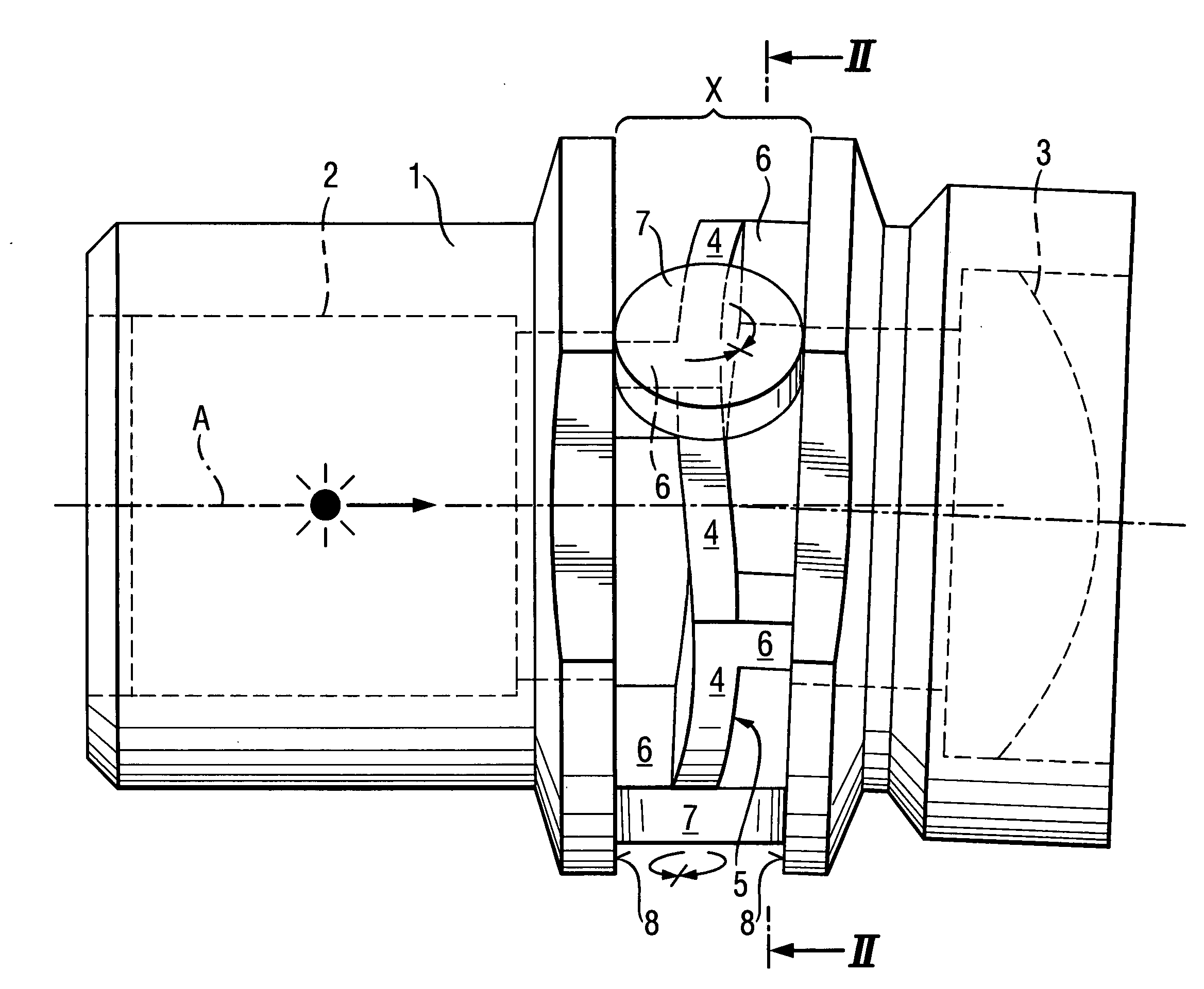
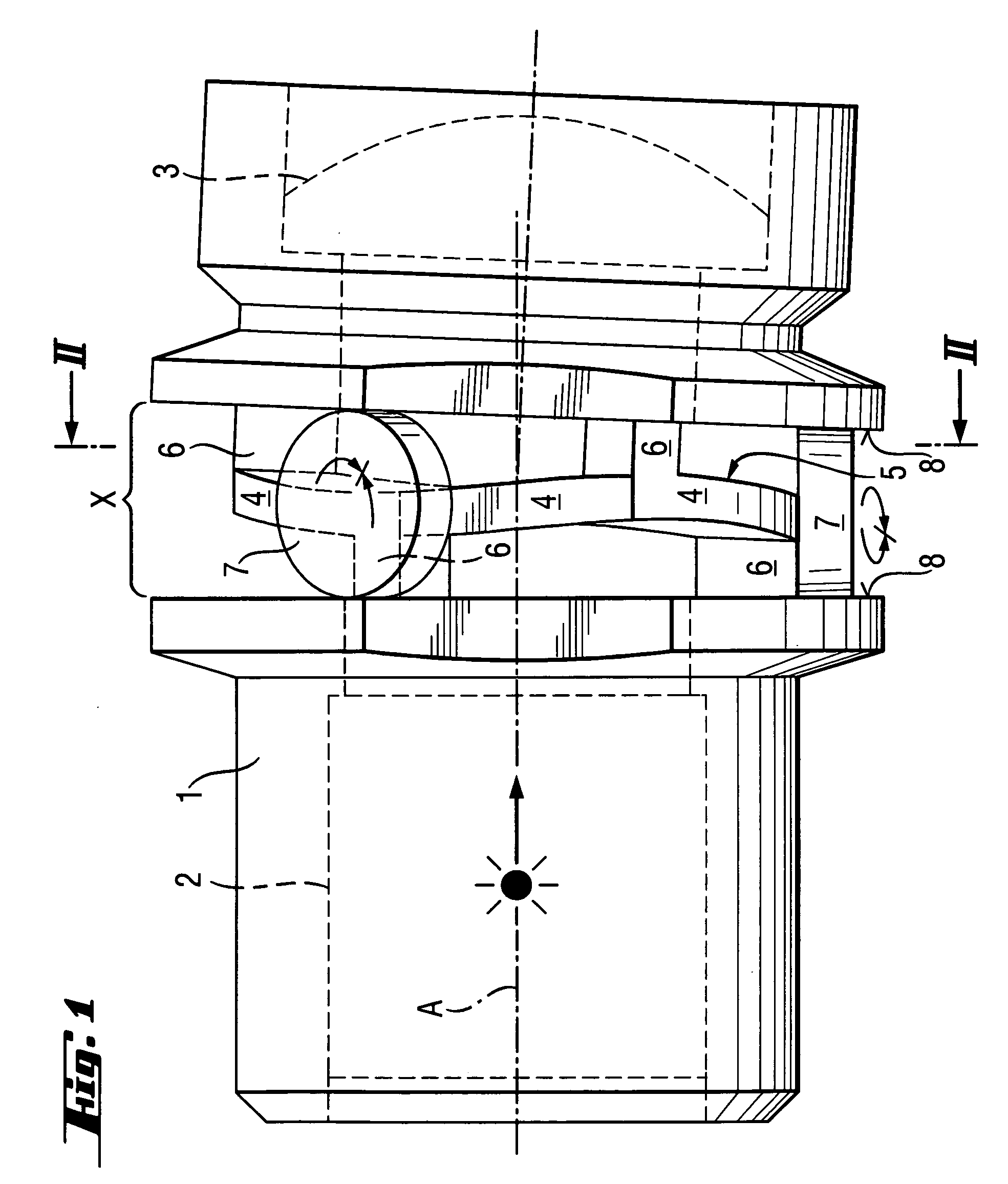
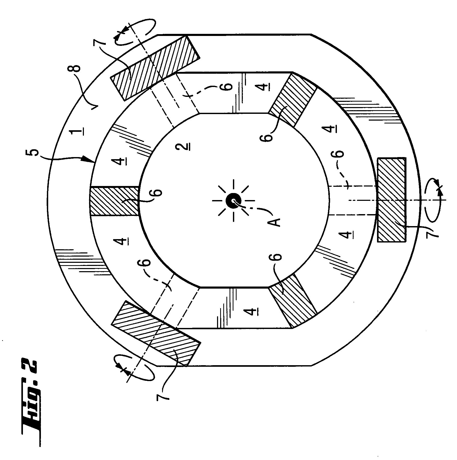
[0023]FIGS. 1 and 2 show an optical assembly according to the present invention the inclination of which relative to an axis A is adjustable. The inventive optical assembly is formed as a collimator optics that is capable of being brought into focus, and has a metal optics carrier 1. In the interior of the optics carrier 1, there are located, coaxially therewith, two optical components in form of a laser diode 2 and a collimator lens 3 which are fixedly connected with the optics carrier 1. The optics carrier 1 has, in its axial intermediate region between the two optical components, a plurality of thin, tangentially oriented deformation webs4 which form together a circumferential deformation ring 5. The circumferential deformation ring 5 is connected with the optics carrier 1 by circumferentially arranged supports 6.

[0024] On each of the opposite sides of the deformation ring (5) there are arranged three supports 6 offset relative to each other by 120°. The supports 6 on the rear s...


PUM


Abstract

An optical assembly, which is adjustable relative to an axis (A), includes an optics carrier (1), at least two optical components (2, 3) fixedly connected with the optics carrier (1) and axially spaced from each other, and at least one thin, partially tangentially oriented, deformation web (4) provided in the optics carrier (1) in an axial intermediate region (X) between the at least two optical components (2, 3)

Description

BACKGROUND OF THE INVENTION [0001] 1. Field of the Invention [0002] The present invention relates to an adjustable optical assembly and, in particular to collimator optics for laser diodes which is capable of being brought into focus. [0003] 2. Description of the Prior Art [0004] Laser diodes require additional collimator optics for parallel orientation of the laser beam. With the collimator optics, after mounting of the laser diode and the collimator lens in an optics carrier, an adjustment of opposite positions relative to each other, which includes axial displacement (focus) and inclination, should be effected. With simple collimator optics, the laser diodes and the collimator lens are secured only after the adjustment has been made. The securing process, e.g., gluing, require some time which represents a drawback at mass production. [0005] According to German utility model DE 9002698U, with collimator optics, centering of the laser diode takes place. The laser diode is axially s...

Claims


Application Information

Patent Timeline
IPC IPC(8): G02B7/02
CPCG02B7/023G02B7/021
Inventor HAEFELE, CHRISTIANSTEFFEN, ROMAN
Owner HILTI AG
Why Eureka
Try Eureka