Magnetic agitator

Inactive Publication Date: 2007-02-15
ASPIRA HLDG
View PDF24 Cites 21 Cited by
  • Summary
  • Abstract
  • Description
  • Claims
  • Application Information

AI Technical Summary

Benefits of technology

[0008] The object of the present invention, therefore, is to create an agitator that does not have the disadvantages of the known devices and to provide a method for operating this agitator.
[0009] In order to at least partially absorb the forces generated during agitation, the agit

Problems solved by technology

It is hard to imagine process engineering, particularly in the biotech sector, the pharmaceutical industry, and the food industry, without mechanically agitated reactors.
Th

Method used


Image

  • Magnetic agitator
  • Magnetic agitator
  • Magnetic agitator

Examples


Example

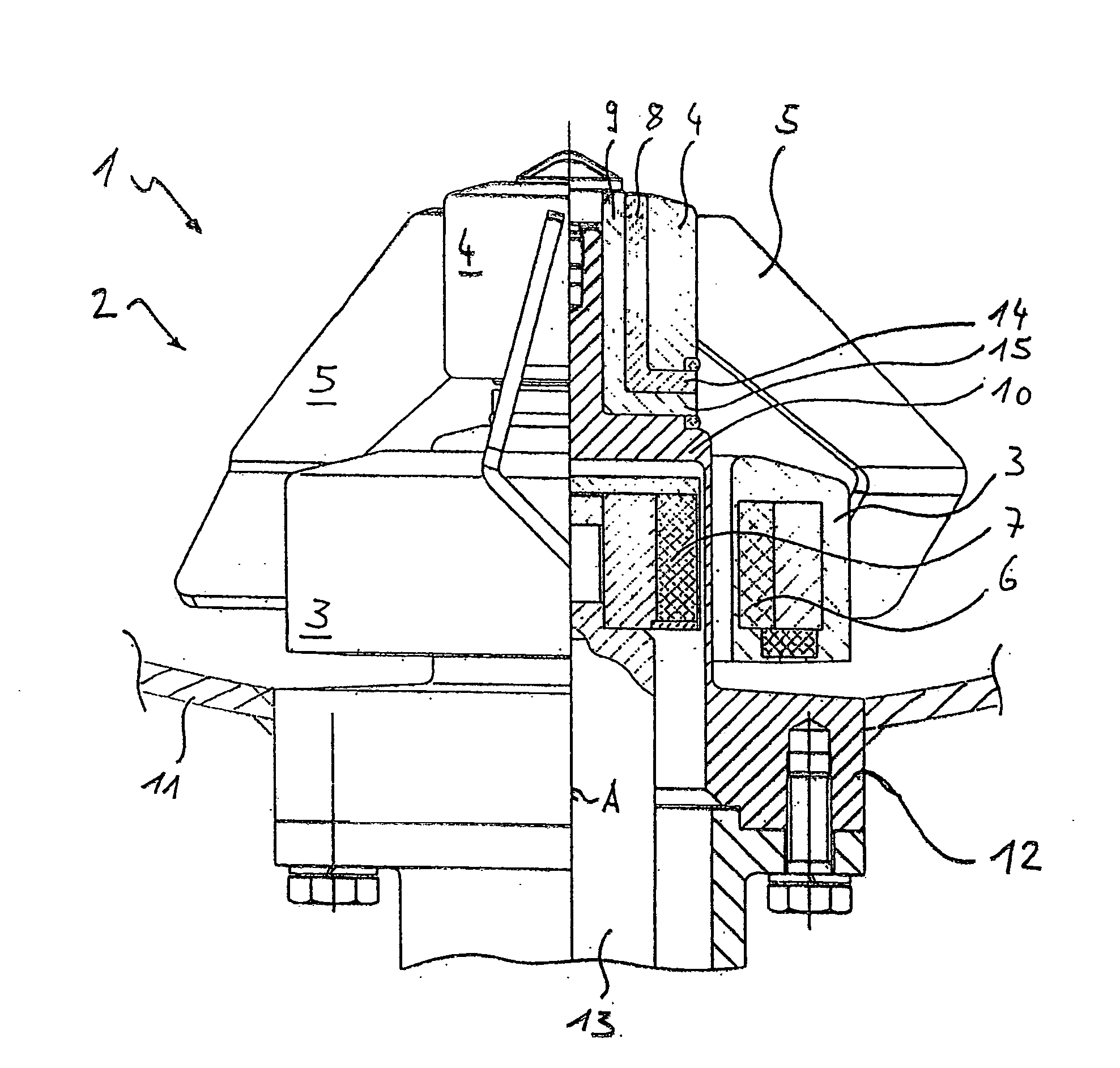
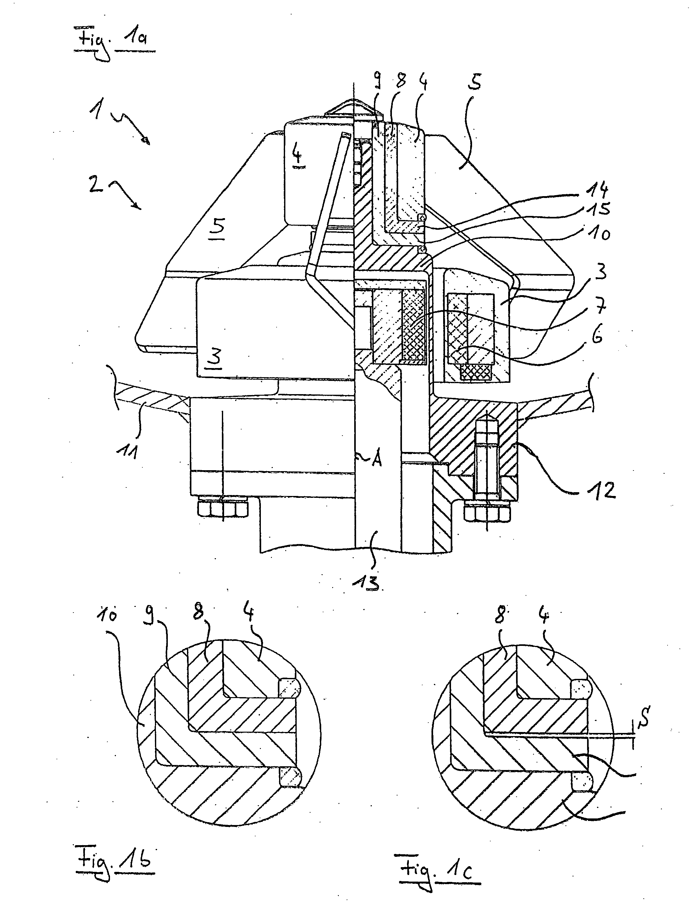
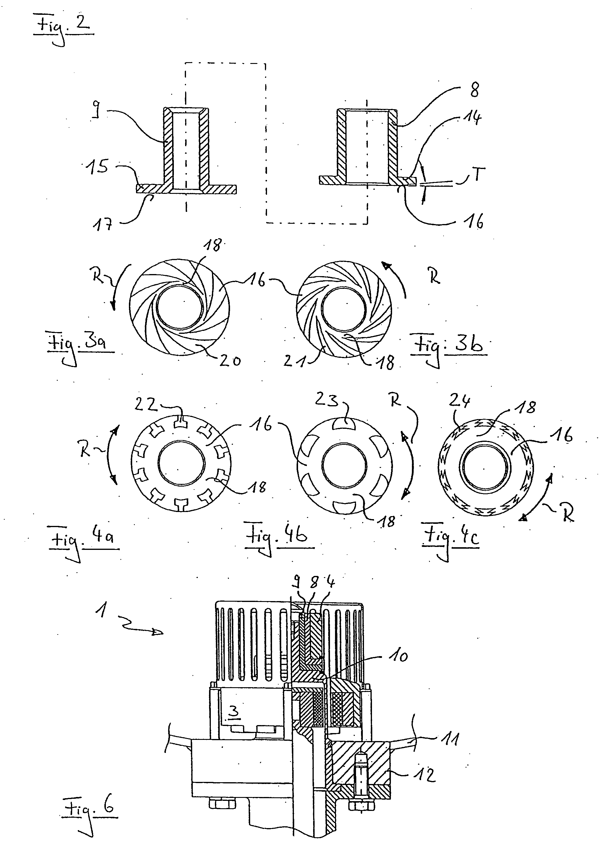
[0025] The agitator 1 according to one preferred embodiment of the present invention shown in FIG. 1a, is based on an impeller for breaking down temperature and concentration gradients in aqueous solutions, which has been successfully manufactured and marketed by the applicant. An agitator head 2 preferably has two rings 3 and 4 coaxial to each other, which are connected to each other via agitating elements 5. A magnetic outer rotor 6 is contained in a lower drive ring 3. In the agitator head according to FIG. 1, a bearing bushing 8 is inserted into an upper bearing ring 4. With the bearing bushing 8, the agitator head 2 is slid onto a protruding, stationary upper bearing pin 9 of a separating vessel 10. Preferably, the bearing is a ceramic slide bearing. The cylindrical, axially oriented portions of the bearing bushing 8 and bearing pin 9 cooperate in a known manner to assure the radial and axial movement of the agitator head. A novel feature of the bearing is that the bearing bush...


PUM


Abstract

A contactlessly, inductively, or magnetically drivable agitator (1) for fluids, in particular for agitating sterile fluids which is equipped with a separating vessel (10) and an agitator head (2), which is supported thereon in an axially and radially movable fashion and is for supporting agitating elements (5). The novel agitator (1) includes means for hydrodynamically generating a fluid film from the medium to be agitated and during operation, the fluid film is formed between at least one stationary part of the separating vessel (10) or a container bottom (11) and at least one part of the rotationally movable agitator head (2) that is equipped with the hydrodynamically acting means. During operation, the fluid film eliminates essentially all of the pressure on the bearing, drastically reduces the wear, and as a result, practically no further abraded material gets into the fluids to be agitated. Such agitators permit maximum speeds of up to 3000 rpm. The agitators are suitable for installation in conventional metal receptacles, but it is preferable to use plastic nonreusable agitators in nonreusable containers.

Description

BACKGROUND OF THE INVENTION [0001] 1. Field of the Invention [0002] The present invention relates to a magnetic agitator for fluids, in particular for agitating sterile fluids and a method for operating such an agitator. [0003] 2. Discussion of Related Art [0004] It is hard to imagine process engineering, particularly in the biotech sector, the pharmaceutical industry, and the food industry, without mechanically agitated reactors. The problematic seal of the agitator shaft has led, for reasons of both sterility and biosafety, to a preference for floating agitator bearings in lieu of packing glands, lip seals, or sliding ring seals. Magnetically coupled agitator systems in which the separating vessel is part of a welding flange in the container wall, thus guaranteeing a hermetic separation of the inside of the container from the surrounding atmosphere, have been disclosed by the applicant and been successfully used in practice. [0005] U.S. Pat. No. 4,993,841 and European Reference EP...

Claims


Application Information

Patent Timeline
IPC IPC(8): B01F13/08
CPCB01F7/00033B01F7/162B01F13/0827F16C2240/40F16C17/10F16C33/1065F16C17/045B01F27/053B01F27/808B01F33/453
Inventor MEIER, HANS PETER
Owner ASPIRA HLDG
Why Eureka
Try Eureka