Liquid crystal display device

a liquid crystal display and display device technology, applied in the direction of thin material processing, instruments, chemistry apparatus and processes, etc., can solve the problems of insufficient vertical viewing angle expansion and low front brightness, and achieve the effect of narrowing the viewing angle and not lowering the front brightness of the display devi

Inactive Publication Date: 2007-02-15
FUJIFILM CORP
View PDF7 Cites 15 Cited by
  • Summary
  • Abstract
  • Description
  • Claims
  • Application Information

AI Technical Summary

Benefits of technology

[0025] The invention has made it possible to provide a liquid crystal display device having the same constitution as that of conventional liquid crystal display devices and having a function of optically compensating the liquid crystal cell therein. Further, the liquid crystal display device of the invention has made it possible to prevent peeping as the brightness thereof in the horizontal direction at the time of black level of display is increased and the viewing angle thereto is narrowed. The display device keeps a broad viewing angle in the horizontal direction, intrinsic to conventional IPS mode display devices. Further, the front brightness of the display device is not lowered, and the invention thus provides a bright IPS mode liquid crystal display device.

Problems solved by technology

However, the viewing angle-controlling film as above has some problems in that the viewing angle expansion in the vertical direction is insufficient and the front brightness lowers.

Method used


Image

  • Liquid crystal display device
  • Liquid crystal display device
  • Liquid crystal display device

Examples


example 1

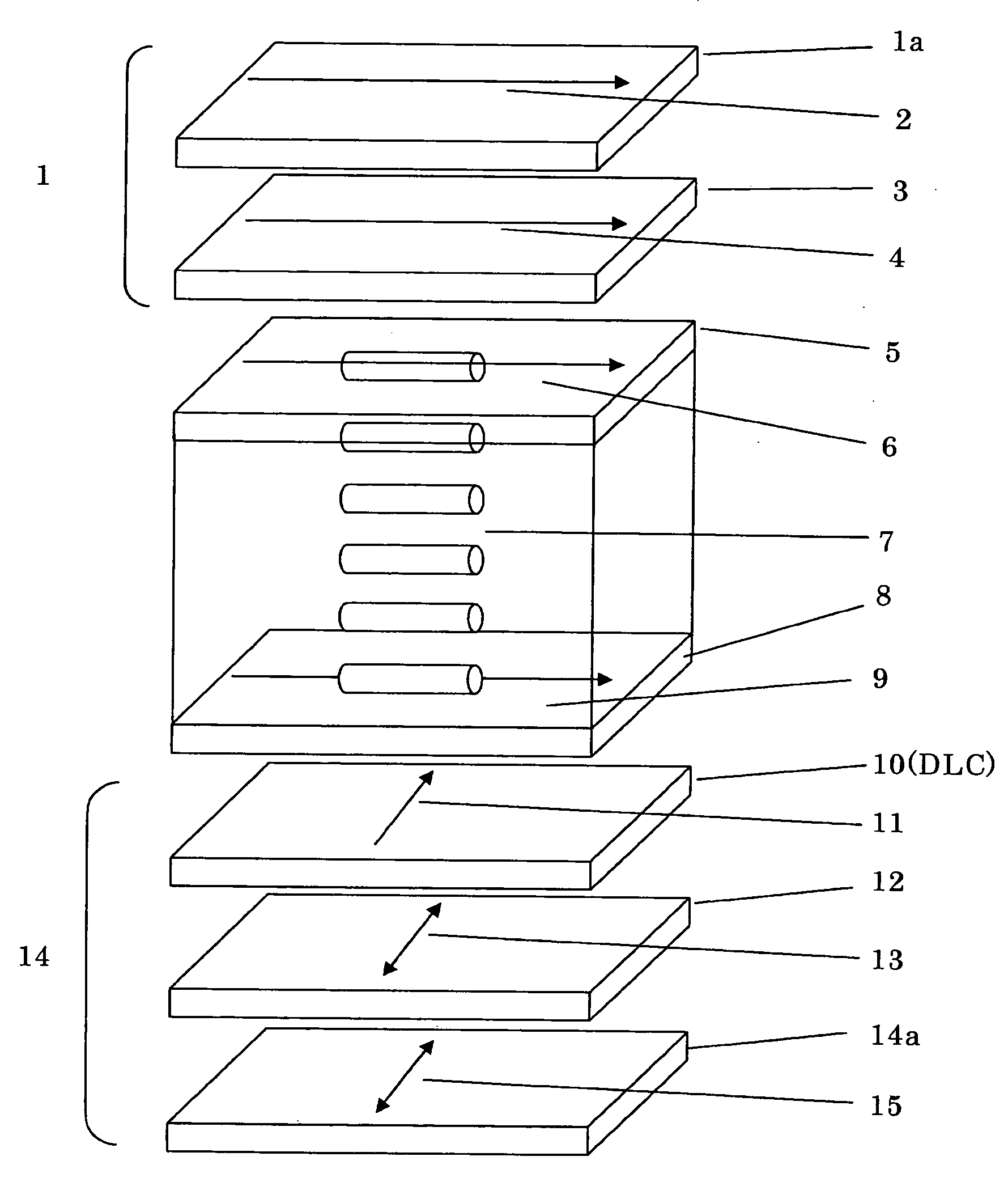
[0155] A liquid crystal display device having the constitution shown in FIG. 1 was fabricated. Briefly, an upper polarizing plate 1, an upper protective film 3, a liquid crystal cell (upper substrate 5, liquid crystal layer 7, lower substrate 8), a lower optically anisotropic layer 10, and a lower polarizing plate 12 were laminated in that order from the viewing side (upper side),; and below the lower polarizing plate, disposed was a backlight with a cold-cathode fluorescent tube (not shown). The constitutive members and methods for producing them are described below.

(Formation of IPS Mode Liquid Crystal Cell)

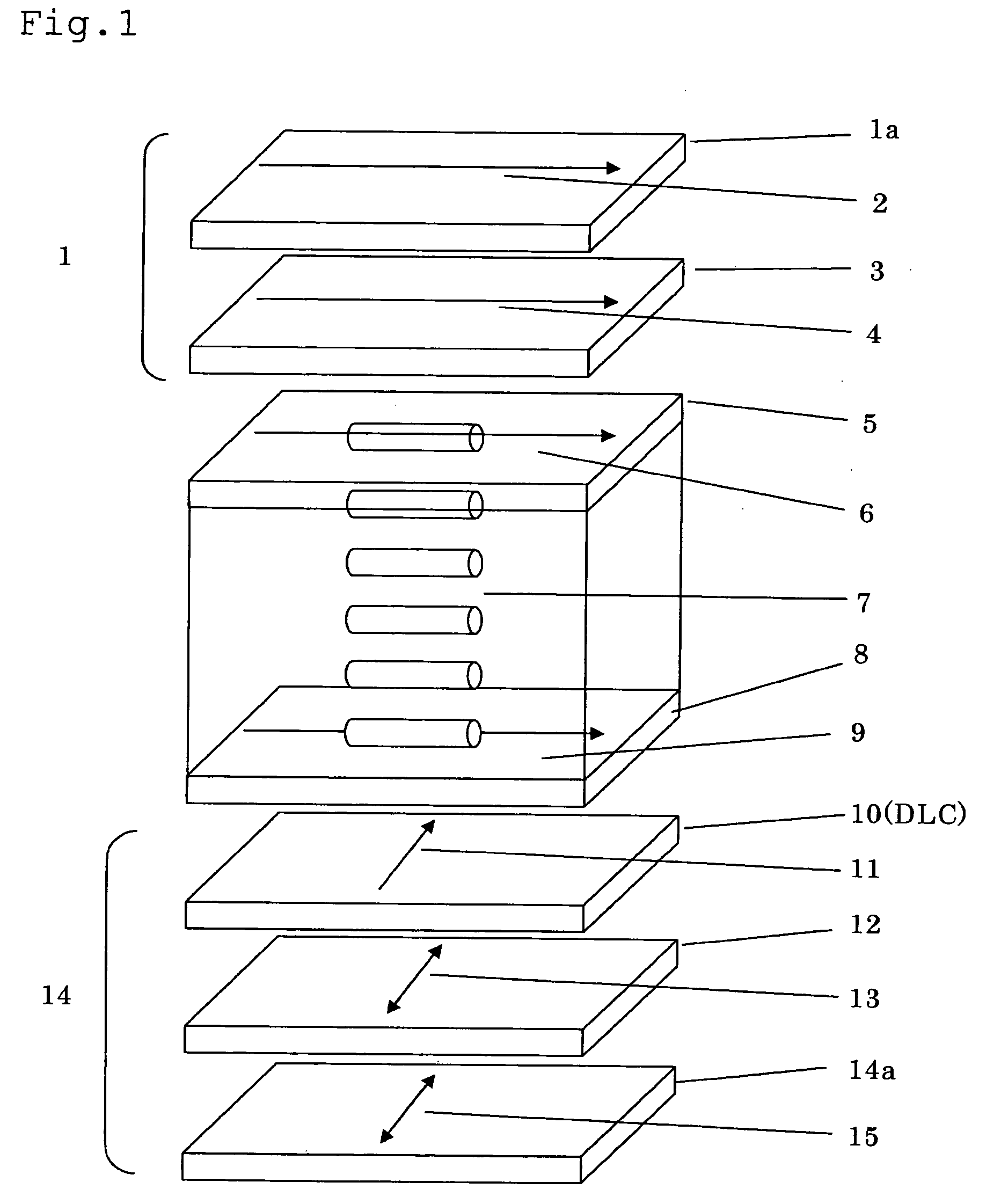
[0156]FIG. 2 shows a cross-sectional view of the liquid crystal display device fabricated herein. On the inner side of one substrate 8 of a pair of substrates, formed is a linear electrode of ITO (this may be a metal such as chromium or aluminium); and an alignment control film (not shown) is formed on it. The rod-shaped liquid crystalline molecules 7 sandwiched between the ...

example 2

[0169] In the liquid crystal display device produced in Example 1, an optically anisotropic layer (upper optically anisotropic layer) of a hybrid-aligned discotic compound was disposed between the upper protective film and the liquid crystal cell, and the alignment control direction of the upper optically anisotropic layer was set at 90 degrees. The other constitution is the same as in Example 1. The viewing angle to obtain a contrast of at least 10 in the horizontal direction was 40 degrees both in the right side and the left side directions. The viewing angle to obtain the contrast of at least 10 in the upper and lower directions was 85°, respectively.

example 3

[0172] An optically anisotropic layer-fitted polarizing plate that had been produced in the same manner as in Example 1 was disposed on the surface of an IPS panel-mounted, commercially-available liquid crystal TV, Hitachi's WO 00 / 7000. The absorption axis direction of the polarizing plate on the front side of the commercially-available TV was 90°; the absorption axis direction of the added polarizing plate was also 90°; and the alignment control direction of the optically anisotropic layer was also 90°. The viewing angle to obtain a contrast of at least 10 in the vertical direction was 85° in the commercially-available TV, and it was reduced to 40° after modified as herein. On the other hand, the viewing angle to obtain a contrast of at least 10 in the vertical direction of the modified TV was 85°, which was the same as that in the commercially-available TV. Accordingly, this Example confirms the following: When a hybrid-aligned optically anisotropic layer-having polarizing plate i...


PUM

PropertyMeasurementUnit
sizeaaaaaaaaaa
sizeaaaaaaaaaa
sizeaaaaaaaaaa

Abstract

A liquid crystal display device comprising a liquid crystal cell containing a nematic liquid crystal material aligned nearly in parallel to the surfaces of the cell at the time of no voltage application thereto, and two polarizers disposed on both outer sides of the liquid crystal cell, wherein the optically anisotropic layer comprising a hybrid-aligned compound is disposed between the liquid crystal cell and one of the polarizers and the alignment control direction of the hybrid-aligned compound is nearly in parallel to absorption axis of any one of the polarizers.

Description

BACKGROUND OF THE INVENTION [0001] 1. Field of the Invention [0002] The present invention relates to a parallel-aligned liquid crystal display device such as typically an IPS (in-plane switching) mode liquid crystal display device. [0003] 2. Description of the Related Art [0004] A liquid crystal display device comprises a liquid crystal cell and a polarizing plate. The polarizing plate comprises a protective film and a polarizer (polarizing film). In general, the polarizing plate is obtained by coloring a polarizer of a polyvinyl alcohol film with iodine, stretching it and then laminating a protective film on both faces thereof. A transmission liquid crystal display device may comprise such a polarizing plate fitted to both sides of the liquid crystal cell thereof, and may further has one or more optical compensatory sheets (films) disposed therein. On the other hand, a reflection liquid crystal display device may generally comprise a reflector, a liquid crystal cell, one or more op...

Claims


Application Information

Patent Timeline
Patent Type & Authority Applications(United States)
IPC IPC(8): C09K19/00
CPCG02F1/13363Y10T428/1041G02F1/134363G02F1/133711C09K2323/031
Inventor HIRAKATA, JUNICHI
Owner FUJIFILM CORP
Why Eureka
Try Eureka