Fluorescent tube attaching structure

Inactive Publication Date: 2007-02-15
JST MFG CO LTD
View PDF12 Cites 24 Cited by
  • Summary
  • Abstract
  • Description
  • Claims
  • Application Information

AI Technical Summary

Benefits of technology

[0015] In addition, the pair of straight portions extend along the fluorescent tube attaching direction, and this provides the following advantage. That is, even if the holder and the fluorescent tube have variations in dimensional errors, the position of the terminal of the fluorescent tube in the attaching direction can be adjusted without applying an excessive f

Problems solved by technology

However, in the documents 1 and 2, there is a risk that conducting failure may occur between the terminal and the connection fitting due to defective soldering.
In addition, the soldering is troublesome.
Therefore

Method used


Image

  • Fluorescent tube attaching structure
  • Fluorescent tube attaching structure
  • Fluorescent tube attaching structure

Examples


Embodiment Construction

[0032] A preferred embodiment of the present invention will be described with reference to the accompanying drawings.

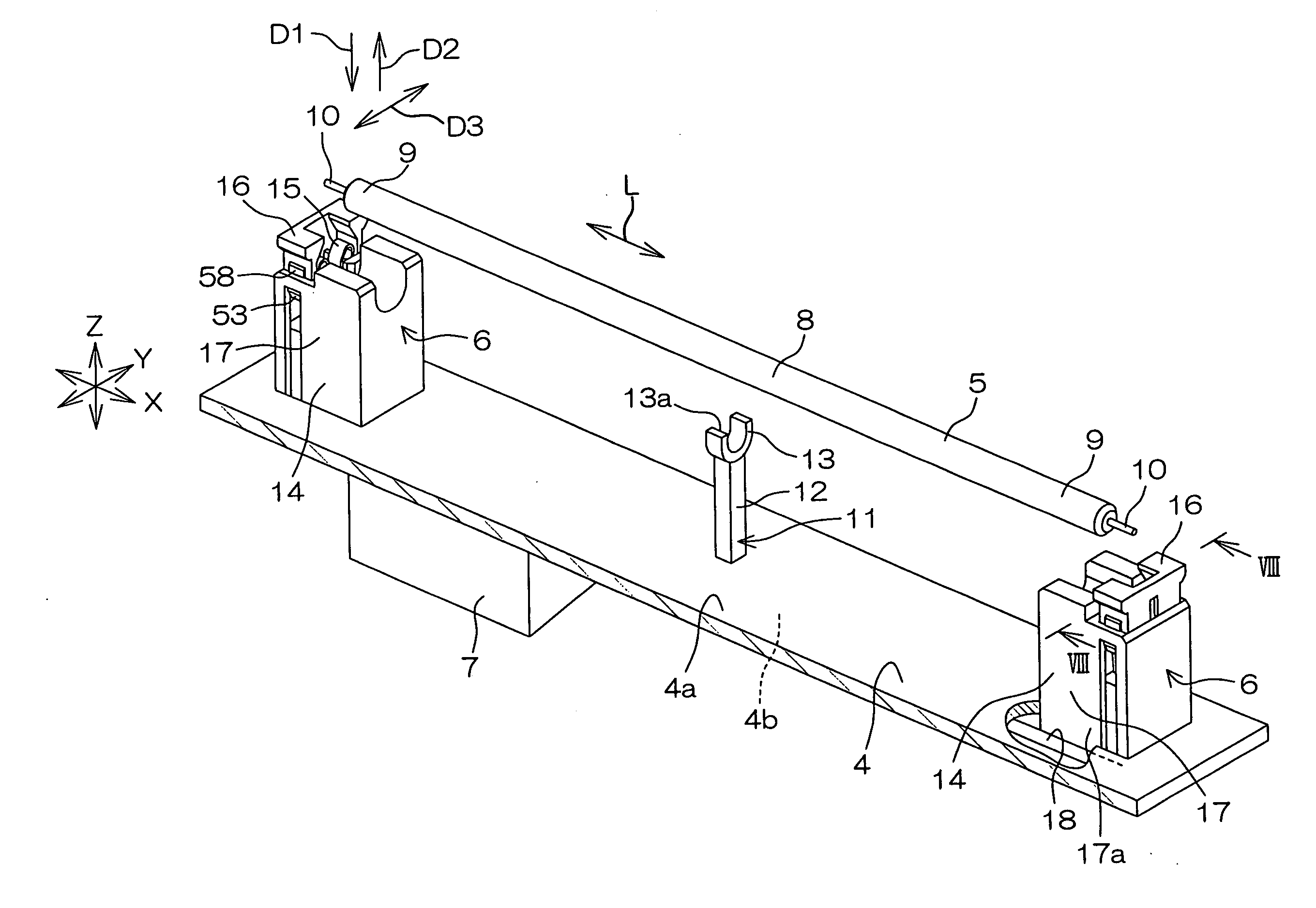
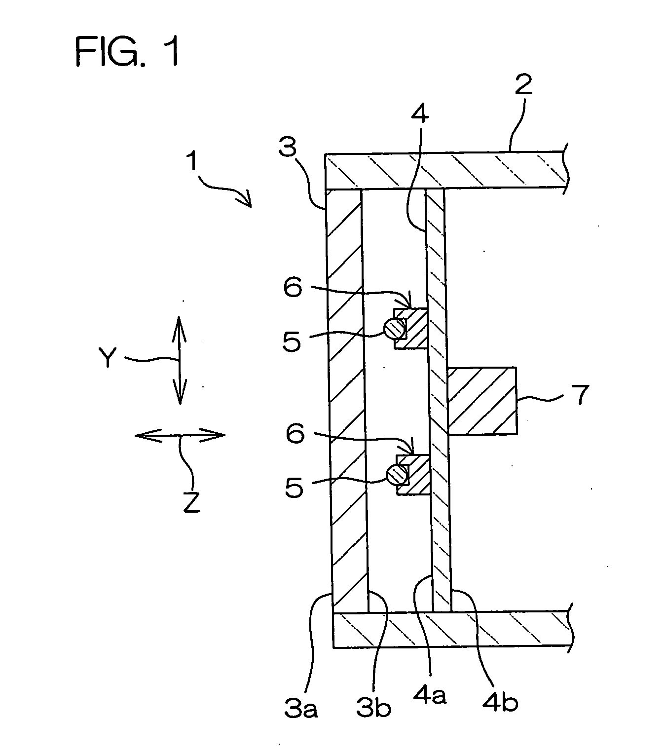
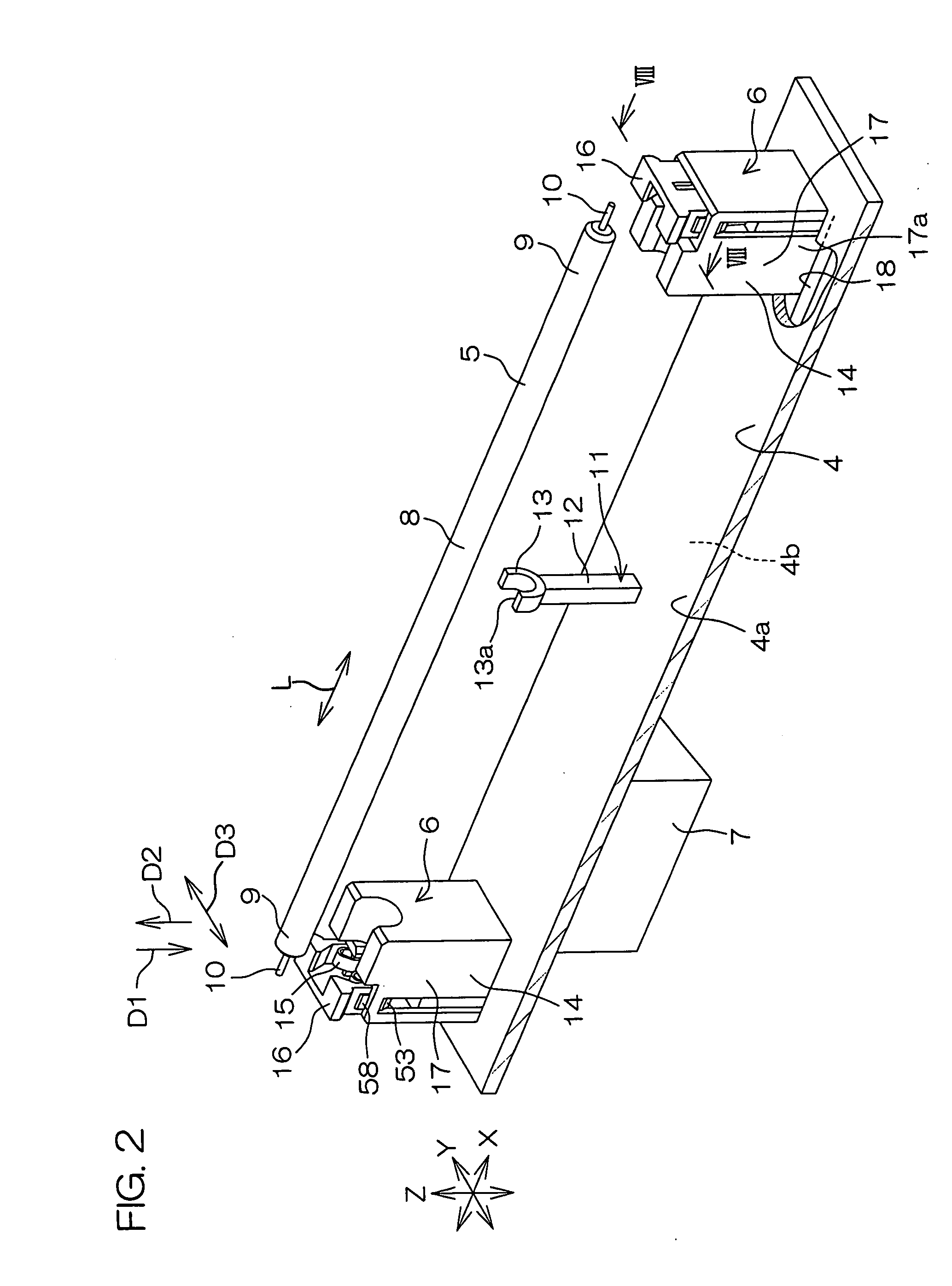
[0033]FIG. 1 is a schematic sectional view showing a general construction of a liquid crystal display device having a fluorescent tube attaching structure according to an embodiment of the present invention. Referring to FIG. 1, the liquid crystal display device 1 is used as, for example, a monitor of a television or a personal computer.

[0034] The liquid crystal display device 1 includes a casing 2, a liquid crystal panel 3, a circuit board 4 disposed in the rear of the liquid crystal panel 3, a plurality of cold cathode fluorescent tubes 5 as fluorescent tubes, electrical connectors 6 (hereinafter, also referred to as connectors, simply), and an inverter circuit 7.

[0035] The liquid crystal panel 3 is a non light-emitting display panel, and is attached to an opening on the front of the casing 2. A front face 3a of the liquid crystal panel 3 faces forward from the c...


PUM


Abstract

A structure for attaching a fluorescent tube includes a base, a holder supported by the base, and a pair of contacts. The holder holds an intermediate portion of the fluorescent tube while restraining the fluorescent tube from moving in a radial direction. To the pair of contacts, terminals of a pair of end portions of the fluorescent tube are respectively attachable in an attaching direction corresponding to the radial direction of the fluorescent tube. Each contact includes a pair of elastic pieces facing each other. The pair of elastic pieces have a pair of straight portions extending substantially straight along the attaching direction and facing each other. On the pair of straight portions, a pair of contact portions for clamping the corresponding terminal of the fluorescent tube therebetween are formed.

Description

BACKGROUND OF THE INVENTION [0001] 1. Field of the Invention [0002] The present invention relates to a attaching structure for a long fluorescent tube. [0003] 2. Description of Related Arts [0004] For example, as connecting structures for terminals of fluorescent tubes such as cold cathode fluorescent tubes to be used as a backlight of a liquid crystal display type television or monitor, the following documents 1 and 2 have been proposed. [0005] Document 1: Japanese Unexamined Patent Publication No. 2001-250605 (Date of publication: Sep. 14, 2001) [0006] Document 2: Japanese Unexamined Patent Publication No. 2004-259645 (Date of publication: Sep. 16, 2004) [0007] In the documents 1 and 2, a connection fitting fixed to one end of an electric wire is soldered to a terminal (electrode) of a cold cathode fluorescent tube. The other end of the electric wire is connected to an inverter circuit via a connector. Electrical power from the inverter circuit is supplied to the cold cathode fluo...

Claims


Application Information

Patent Timeline
IPC IPC(8): H01R33/08H01R33/02
CPCH01R33/7692H01R33/0827F21V19/00G02F1/1335H01J61/78
Inventor MIYAZONO, KATSUNORI
Owner JST MFG CO LTD
Why Eureka
Try Eureka