Rebar positioner for masonry construction

a positioner and masonry technology, applied in the field of masonry construction, can solve the problems of unstable positioner, difficulty in rebar positioning, and numerous problems, and achieve the effect of increasing the attachment strength and widthwise stability

Inactive Publication Date: 2007-02-22
MR CROWELL DEAN
View PDF12 Cites 9 Cited by
  • Summary
  • Abstract
  • Description
  • Claims
  • Application Information

AI Technical Summary

Benefits of technology

[0011] The positioner also comprises a crossbar attached to the spine near the spine midsection. The crossbar has a crossbar midsection, a first crossbar end, and a second crossbar end. The crossbar is preferably substantially perpendicular to the spine. In preferred embodiments, the crossbar is also in contact with the ring to increase the strength of attachment, yet embodiments that do not utilize such ring contact are still within the scope of the present invention. Still, in other embodiments, the crossbar may be attached to the spine through the ring, rather than attached directly to t

Problems solved by technology

Using traditional positioners however, such as, for example, the positioner shown in FIG. 1, creates numerous problems.
But, because positioner 12 is itself prone to excessive movement relative to block 10, requisite rebar positioning can be difficult.
This adds to positioner instability, because such vibration further results in the movement of the rebar positioners.
In addition to the general positioning problems that can occur as positioners move generally, another specific problem arises when positioners move widthwise or irregularly.
When positioners move widthwise or irregularly they have an increased tendency to punch out mortar on either the exterior or interior portion of the wall.
Such problems require extensive and costly repair.
While

Method used


Image

  • Rebar positioner for masonry construction
  • Rebar positioner for masonry construction
  • Rebar positioner for masonry construction

Examples


Embodiment Construction

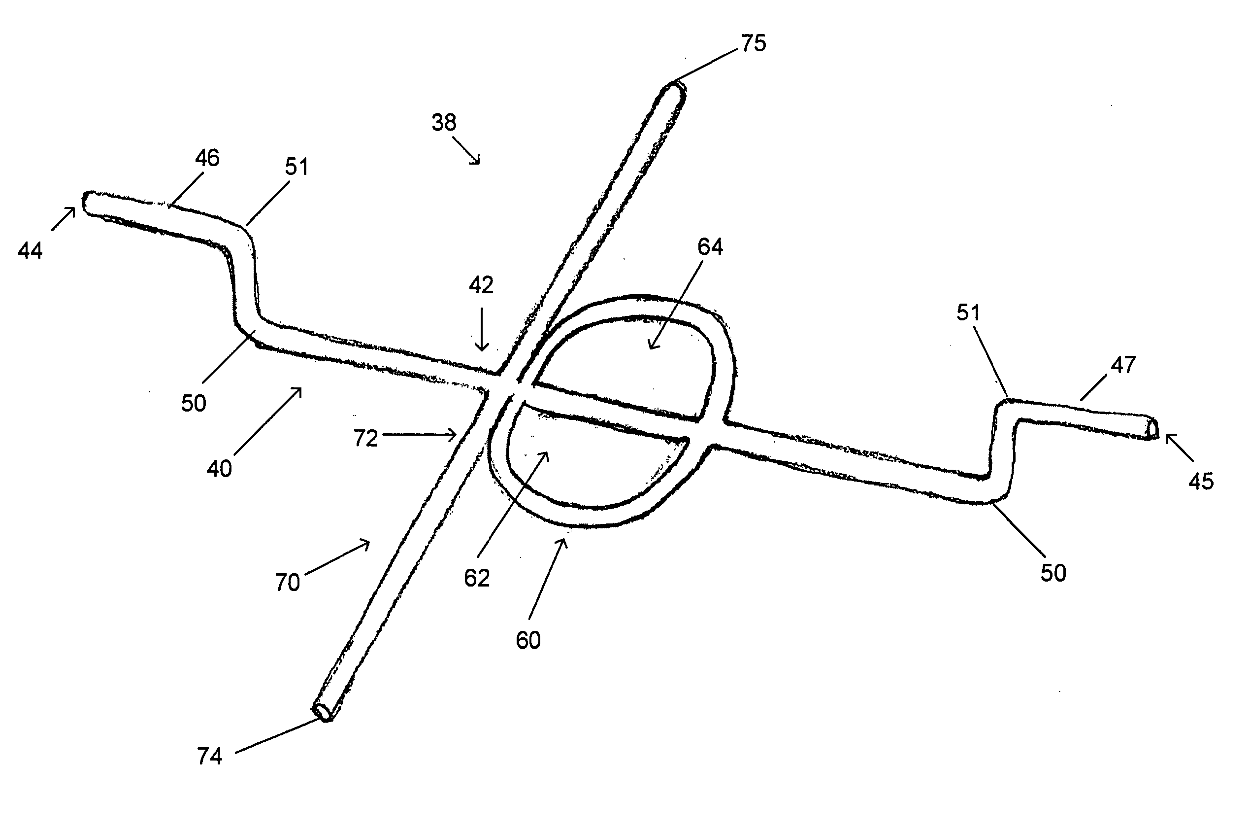
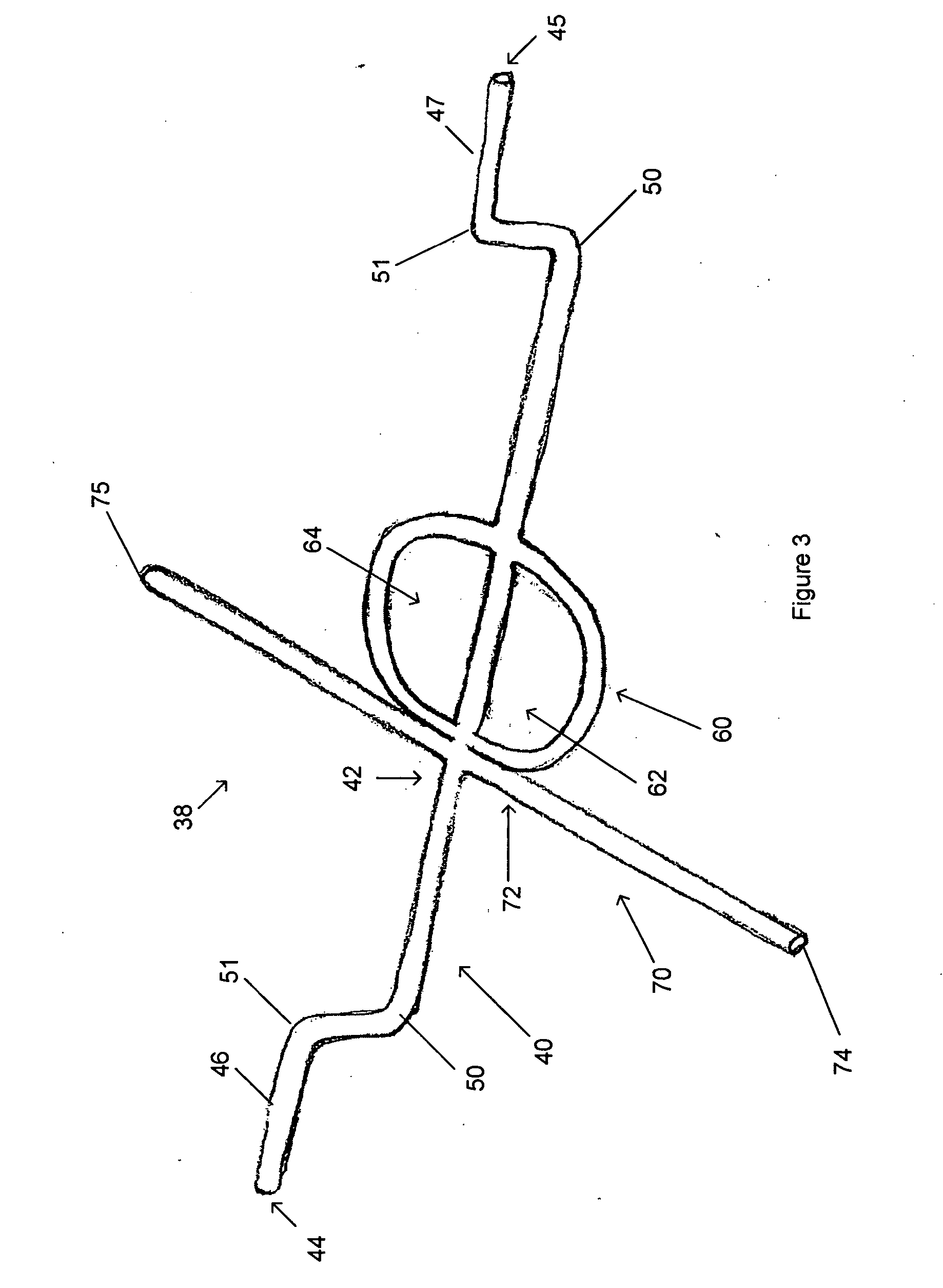
[0020]FIG. 3 shows a rebar positioner 38 according to a preferred embodiment of the present invention. Positioner 38 comprises a spine 40 having a spine midsection 42, a first spine end 44, and a second spine end 45. Positioner 38 includes a first spine rest 46 located at first spine end 44 and a second spine rest 47 located at second spine end 45.

[0021] In the depicted embodiment, both spine rests 46 and 47 are integral with spine 40. While spine 40 could be constructed of numerous materials, e.g. various ceramics, plastics, metals and woods, preferably, spine 40 of the present embodiment is constructed of nine gauge steel wire. Such wire is ideal because it facilitates the shaping of the spine and provides the requisite durability needed for construction. For example, as represented by FIG. 3, spine 40 is bent at points 50 and 51 to form the spine rests 46 and 47 and to offset spine rests 46 and 47 from spine 40. While the integral formation of the spine rests 46 and 47 from the ...


PUM


Abstract

A rebar positioner for positioning rebar in concrete masonry units has a spine having a midsection, a first end, and a second end. The first end may be partially offset to form a first rest and the second end may be partially offset to form a second rest. The positioner includes a ring, which may be bifurcatingly attached to the spine. The positioner also includes a crossbar attached to the spine.

Description

[0001] This application claims the benefit of U.S. Provisional Application No. 60 / 708,650, filed Aug., 16, 2005.BACKGROUND INFORMATION [0002] In masonry construction, particularly for the construction of retail buildings, such as big box retailers or drug stores, sidewalls are typically made of stacked concrete masonry units (CMUs), commonly called cinder blocks. CMUs are generally rectangular, right parallelepipeds having peripheral sidewalls and a central core. Typically the central core includes two channels extending between the two longer edges of the parallelepiped and separated a medial wall. During construction, CMUs are stacked by offsetting the CMUs of odd and even courses so the various channels of the CMUs align vertically. For example, the left channel of a CMU in one course is positioned over the right channel of a CMU in the course above or below. Such staggering, while increasing stability, also creates relatively continuous vertical channels extending from course to...

Claims


Application Information

Patent Timeline
IPC IPC(8): E04C5/16
CPCE04C5/168E04G21/185E04C5/18
Inventor CROWELL, DEAN
Owner MR CROWELL DEAN
Why Eureka
Try Eureka