Foldable honeycomb structure and method for making the same

a honeycomb and foldable technology, applied in the direction of shutters/movable grilles, paper/cardboard articles, door/window protective devices, etc., can solve the problems of increased dyeing difficulty and difficulty in manufacturing strips, and achieve the effect of reducing cost and process time, reducing the difficulty of dyeing, and precise gluing position

Inactive Publication Date: 2007-02-22
METAL INDS RES & DEV CENT +1
View PDF87 Cites 24 Cited by
  • Summary
  • Abstract
  • Description
  • Claims
  • Application Information

AI Technical Summary

Benefits of technology

[0018] The main object of the present invention is to provide a method for making a foldable honeycomb structure, wherein the gluing positions are on at least one of exposed outside surfaces. As a result, it need not open the longitudinal margins during the process of applying the longitudinal glue lines, which can avoid the deformation of the strip and have a precise gluing position. Moreover, since the conventional trip opener is omitted, the manufacture equipment can be more simplified, thus reducing the cost and the process time.

Problems solved by technology

The most important problem of the honeycomb structure and method for making the same described above resides in that the glue lines are between the central portions and the longitudinal margins.
Furthermore, another problem of the above honeycomb structure and method for making the same resides in that it employs the same strip, and if a manufactured honeycomb structure is desired to have two sides of different colors, the difficulty in dyeing will be increased; or if a manufactured honeycomb structure is desired to have two sides with different material properties, it is very difficult to manufacture the strip.

Method used


Image

  • Foldable honeycomb structure and method for making the same
  • Foldable honeycomb structure and method for making the same
  • Foldable honeycomb structure and method for making the same

Examples


first embodiment

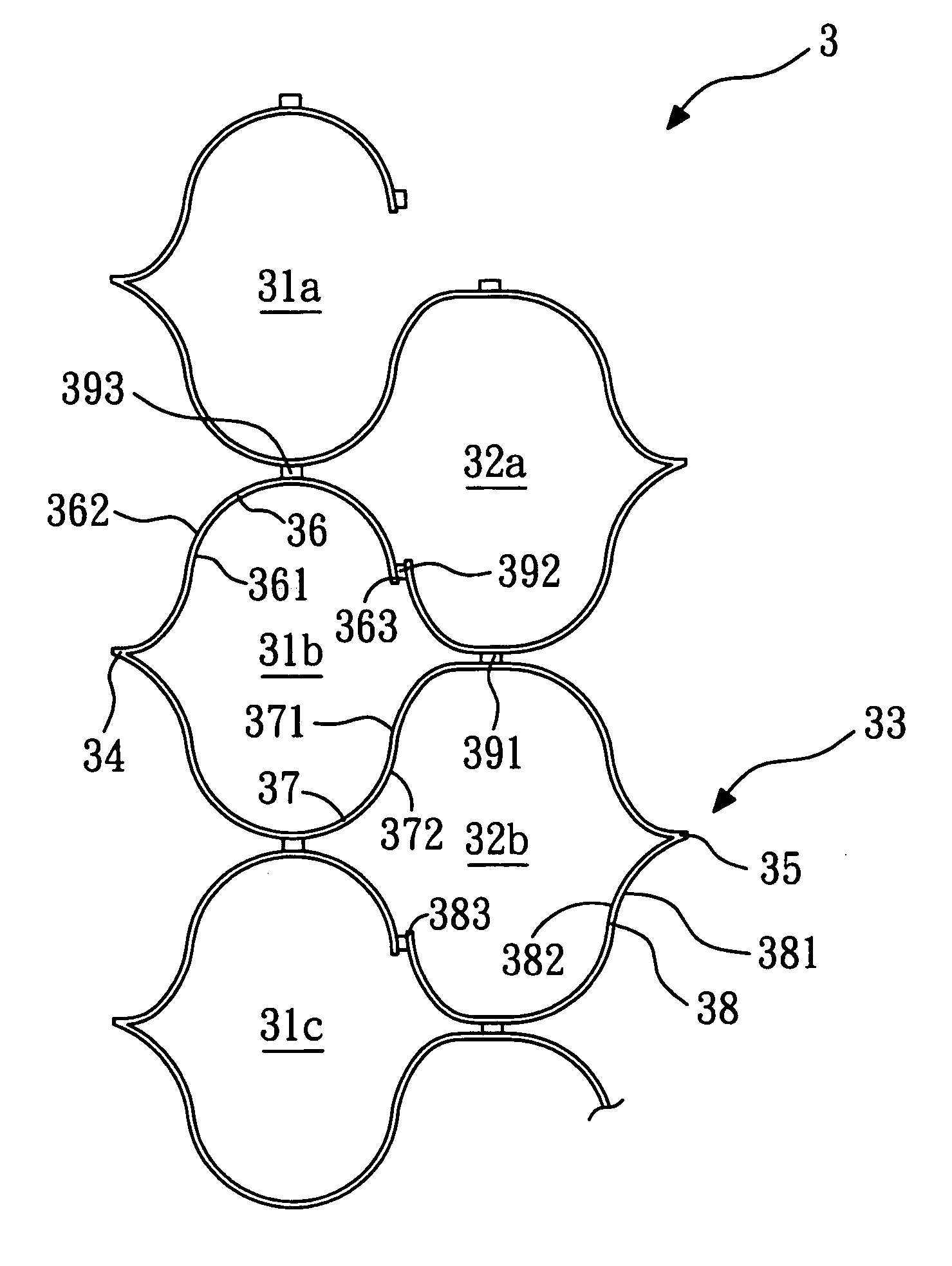
[0043] Referring to FIG. 6, a schematic sectional view of a foldable honeycomb structure in the present invention is shown. The foldable honeycomb structure 3 is applied to the thermal insulation devices such as window curtain or shield curtain, and can be texture or non-texture. The honeycomb structure 3 is of a double cell row structure, in which reference numbers 31a, 31b, 31c, 32a, 32b refer to a cell respectively, the cells 31a, 31b, 31c refer to a first row, and the cells 32a, 32b refer to a second row.

[0044] Referring to FIGS. 7a to 7d, schematic views of a method for making the foldable honeycomb structure in the first embodiment of the present invention of FIG. 6 are shown. First, referring to FIG. 7a, a plurality of flat strips 33 each has a length extending longitudinally are provided. It is to be noted that one strip 33 is illustrated in the embodiment. The strip 33 has a first surface 331 and a second surface 332.

[0045] Next, referring to FIG. 7b, a first longitudinal ...

second embodiment

[0052] Referring to FIG. 8, a schematic sectional view of a foldable honeycomb structure in the present invention is shown. The foldable honeycomb structure 4 is a four-cell row structure.

[0053] Referring to FIGS. 9a to 9d, schematic views of a method for making a foldable honeycomb structure in the second embodiment of the present invention are shown. The method for making the present embodiment is substantially the same as that of the first embodiment, except that two more bonding lines are formed during the gluing step of the present embodiment. First, referring to FIG. 9a, a plurality of flat strips 33 each has a length extending longitudinally are provided. It is to be noted that one strip 33 is illustrated in the embodiment. The strip 33 has a first surface 331 and a second surface 332.

[0054] Next, referring to FIG. 9b, a first longitudinal crease 34 and a second longitudinal crease 35 are formed on the strip 33, so as to define a first longitudinal margin 36, a central porti...

third embodiment

[0062] Referring to FIG. 10, a schematic sectional view of a foldable honeycomb structure in the present invention is shown. The foldable honeycomb structure 40 is a four-cell row structure.

[0063] Referring to FIGS. 11a and 11b, schematic views of a method for making the foldable honeycomb structure in the third embodiment of the present invention of FIG. 10 are shown. The method for making the present embodiment is substantially the same as that of the second embodiment, except that in the present embodiment the width of the first longitudinal margin 36 is different from that of the second longitudinal margin 38, and the fifth bonding line 395 is in a different position. Preferably, in the present embodiment, the ratio of width of the first longitudinal margin 36 to the width of the second longitudinal margin 38 is approximately more than 3:2. In the present embodiment, the fifth bonding line 395 is on the second surface 362 of the first longitudinal margin 36 of the first exposed ...


PUM

PropertyMeasurementUnit
lengthaaaaaaaaaa
widthaaaaaaaaaa
structureaaaaaaaaaa

Abstract

The present invention relates to a foldable honeycomb structure and method for making the same. The method comprises (a) providing a plurality of flat strips; (b) forming a pair of longitudinal creases in each strip thereby defining the first two longitudinal margins of each strip and a central portion of each strip between the creases; (c) folding each strip along said creases so that each folded strip has two exposed outside surfaces; (d) applying at least three longitudinal glue lines to the exposed outside surface of each folded strip; and (e) stacking the glued strips. As a result, it need not open the longitudinal margins during the process of applying the longitudinal glue lines, which can avoid the deformation of the strip and have a precise gluing position.

Description

BACKGROUND OF THE INVENTION [0001] 1. Field of the Invention [0002] The present invention relates to a foldable honeycomb structure and the method for making the same, and particularly relates to a foldable honeycomb structure made through a simple process and the method for making the same. [0003] 2. Description of the Related Art [0004] Referring to FIG. 1, a schematic sectional view of a first kind of conventional foldable honeycomb structure is shown. The conventional foldable honeycomb structure 1 is applied to thermal insulation devices such as window curtain, and can be texture or non-texture, as shown in FIG. 2. Referring to FIG. 1, the honeycomb structure 1 is a double cell row structure, in which the reference numbers 11a, 11b, 11c, 12a, 12b and the like refer to a cell, the cells 11a, 11b, 11c refer to a first row, and the cells 12a, 12b refer to a second row. [0005] Referring to FIGS. 3a to 3d, schematic views of a method for making the conventional foldable honeycomb st...

Claims


Application Information

Patent Timeline
Patent Type & Authority Applications(United States)
IPC IPC(8): A47H5/00
CPCE06B9/262Y10T156/1003Y10T156/1051E06B2009/2627
Inventor SUN, YI-WEILU, CHIN-YUANCHENG, LI-MINGTSAI, KUEI-LIN
Owner METAL INDS RES & DEV CENT
Why Eureka
Try Eureka